Chapter: Special Electrical Machines : Stepping Motor
Drive System and Control Circuitry for Stepper Motor
DRIVE SYSTEM AND CONTROL
CIRCUITRY FOR STEPPER MOTOR
1. DRIVE SYSTEM
The
stepper motor is a digital device that needs binary (digital) signals for its
operation .Depending on the stator construction two or more phases have to be
sequentially switched using a master clock pulse input. The clock frequency determines
the stepping rate, and hence the speed of the motor. The control circuit
generating the sequence is called a translator or logic sequencer.
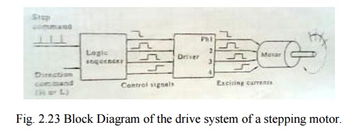
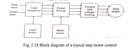
The fig
2.38 shows the block diagram of a typical control circuit for a stepper motor.
It consists of a logic sequencer, power driver and essential protective
circuits for current and voltage limiting. This control circuit enables the
stepper motor to be run at a desired speed in either direction. The power
driver is essentially a current amplifier, since the sequence generator can
supply only logic but not any power. The controller structure for VR or hybrid
types of stepper motor
2. LOGIC SEQUENCER
The logic
sequencer is a logic circuit which control the excitation of the winding
sequentially, responding to step command pulses. A logic sequencer is usually
composed of a shifter register and logic gates such as NANDs, NORs etc. But one
can assemble a logic sequencer for a particular purpose by a proper combination
of JK flip flop, IC chips and logic gate chips.
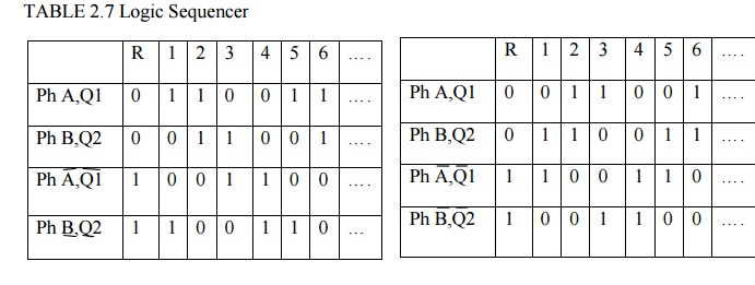
Two
simple types of sequencer build with only two JK-FFs are shown in fig 2.39 for
unidirectional case. Truth tables for logic sequencer also given for both the
directions.
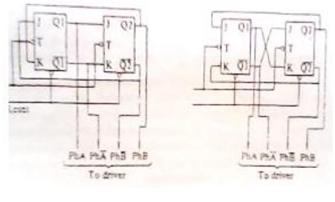
Fig.2.25 A unidirectional logic sequencer for two
phase on operation of a two phase hybrid motor
The
corresponding between the output terminals of the sequencer and the phase
windings to be controlled is as follows.
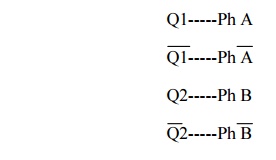
If Q1 is
on the H level the winding Ph A is excited and if Q1is on L level, Ph A is not
excited.
To
reserve the rotational direction, the connection of the sequencer must be
interchanged. The direction switching circuits shown in fig 2.40 may be used
for this purpose. The essential functions being in the combination of three
NAND gates or two AND gates and a NOR gate.
![]()
![]()
3. Power Driver Circuit
The
number of logic signals discussed above is equal to the number of phases and
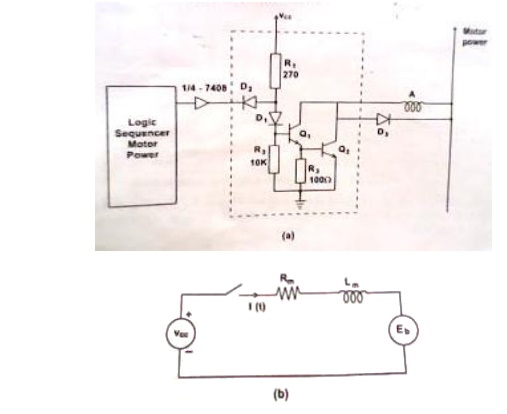
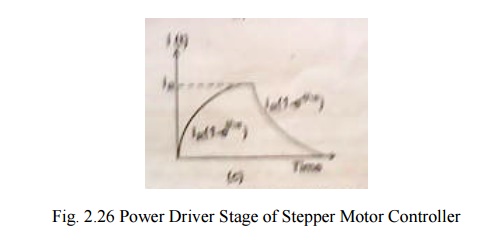
the power circuitry is identical for all phases. Fig. 2.44(a) shows the
simplest possible circuit of one phase consisting of a Darlington pair current
amplifier and associated protection circuits. The switching waveform shown in
fig. 2.44(c) is the typical R-L response with an exponential rise followed by
decay at the end of the pulses.
In view
of the inductive switching operation, certain protective elements are
introduced in the driver circuit. These are the inverter gate 7408, the forward
biased diode D1 and the freewheeling diode D. The inverter IC provides some
sort of isolation between the logic circuit and the power driver.
There are
some problems with this simple power circuit. They can be understood by
considering each phase winding as a R-L circuit shown in fig. 2.44(b) subject
to repetitive switching. On application of a positive step voltage, the current
rises exponentially as

Where
I=V/R – rated current and
Ԏ=L/R
winding time constant.
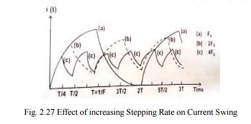
In
practice, the time constant Ԏ limits the rise and fall of current in the
winding. At low stepping rate the current rises to the rated value in each ON
interval and falls to zero value in each OFF interval. However as the switching
rate increases, the current is not able to rise to the steady state, nor fall
down to zero value with in the on/off time intervals set by the pulse waveform.
This in effect, smoothens the winding current reducing the swing as shown in
fig. 2.45. As a result the torque developed by the motor gets reduced
considerably and for higher frequencies, the motor just ‗vibrates‘ or
oscillates within one step of the current mechanical position.
In order
to overcome these problems and to make improvement of current build up several
methods of drive circuits have been developed.
For
example when a transistor is turned on to9 excite a phase, the power supply
must overcome effect of winding inductances has tendency to oppose the current
built up. As switching frequency increases the position that the buildup time
takes up within the switching cycle becomes large and it results in decreased
torque and slow response.
4. Improvement of current
buildup/special driver circuit
(a) Resistance drive (L/R drive)
Here the
initial slope of the current waveform is made higher by adding external resistance
in each winding and applying a higher voltage proportionally. While this
increases the rate of rise of the current, the maximum value remains unchanged
as shown in fig. 2.46.
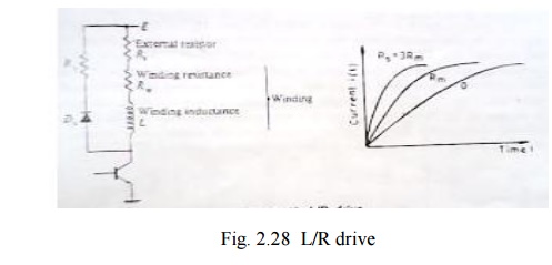
The circuit time constant is now reduced and the motor is able to develop normal torque even at high frequencies. The disadvantage of this method is Flow of current through external resistance causesI2R losses and heating. This denotes wastage of power as far as the motor is concerned.
In order
to reach the same steady state current IR as before, the voltage
required
To be
applied is much higher than before. Hence this approach is suitable for small
instrument stepper motor with current ratings around 100 mA, and heating is not
a major problem.
(b) Dual voltage driver (or)
Bi-level driver
To reduce the power dissipation in the driver and
increase the performance of a stepping motor, a dual-voltage driver is used.
The scheme for one phase is shown in fig. 2.47.
When a
step command pulse is given to the sequencer, a high level signal will be put
out from one of the output terminal to excite a phase winding. On this signal
both T1 and T2 are turned on, and the
higher voltage EHwill be applied to the winding. The diode D1 is now
reverse biased to isolate the lower voltage supply. The current build up
quickly due to the higher voltage EH.
The time constant of the monostable multivibrator is selected so that
transistor T1 is turned off when the winding current exceeds the rated current
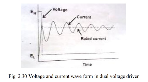
by a little. After the higher
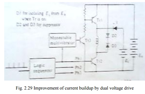
Voltage
source is cut off the diode is forward biased and the winding current is
supplied from the lower voltage supply. A typical current wave form is shown in
fig. 2.48.
When the dual voltage method is employed for the two phase on drive of a two phase hybrid motor, the circuit scheme will de such as that shown in fig.2.49. Two transistor T 1 &T 2 and two diodes D1 and D2 are used for switching the higher voltage. In dual voltage scheme as the stepping rate is increased, the high voltage is turned on for a greater percentage of time.
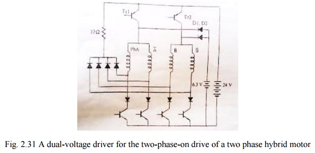
This
drive is good and energy efficient. However it is more complex as it requires
two regulated power supplies EH& EL end two power transistor switches Tr1
& Tr2 and complex switching logic. Hence it is not very popular.
(c)Chopper drive
Here a
higher voltage 5 to 10 times the related value is applied to the phase winding
as shown in fig.2.50(a) and the current is allowed to raise very fast. As soon
as the current reaches about 2 to 5% above the rated current, the voltage is
cut off ,allowing the current to decrease exponentially. Again as the current
reaches some 2 to 5% below the rated value, the voltage is applied again. The
process is repeated some 5-6 times within the ON period before the phase is
switched off. During this period the current oscillates about the rated value
as shown in fig. A minor modification is to chop the applied dc voltage at a
high frequency of around 1khz, with the desired duty cycle so as to obtain the
average on-state current equal to the rated value.
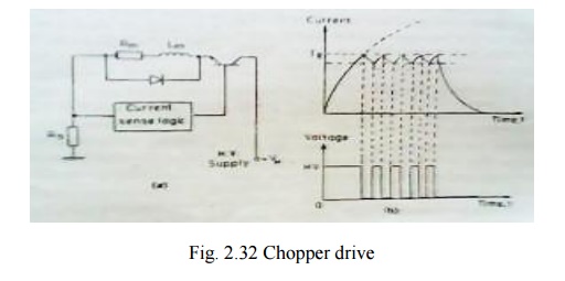
The
chopper drive is particularly suitable for high torque stepper motors. It is
ener4gy efficient like the bi-level drive but the control circuit is simpler.
(d) Problems with driver circuits
A winding
on a stepping motor is inductive and appears as a combination of inductance and
resistance in series. In addition, as a motor revolves a counter emf is
produced in the winding. The equivalent circuit to a winding is hence, such as
that shown for designing a power driver one must take into account necessary
factors and behavior of this kind of circuit. Firstly the worst case3
conditions of the stepping motor, power transistors, and supply voltage must be
considered. The motor parameters vary due to manufacturing tolerance and
operating conditions. Since stepping motors are designed to deliver the highest
power from the smallest size, the case temperature can be as high as about
100°c and the winding resistance therefore increases by 20 to 25 per cent.
Suppressor circuits
These
circuits are needed to ensure fast decay of current through the winding when it
is turned off. When the transistor in the above fig is turned off a high
voltage builds up to Ldi/dt and this voltage may damage the transistor. There
are several methods of suppressing this spike voltage and protecting the
transistor as shown in the following.
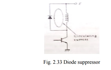
(a) Diode suppressor
If a
diode is put in parallel with the winding in the polarity as shown in fig. a
circulating current will flow after the transistor is turned off, and the
current will decay with time. In this scheme, no big change in current appears
at turn off, and the collector potential is the supply potential E plus the
forward potential of the diode. This method is very simple but a drawback is
that the circulating current lasts for a considerable length of time and it
produces a braking torque.
(b)Diode-Resistor suppressor
A
resistor is connected in series with the diode as shown in fig to damp quickly
the circulating current. The voltage VCE applied to the collector at turn-off
in this scheme is
VCE=E+IRS+VD
Where E=
supply potential
I=
Current before turning off
Rs-resistance
of suppressor resistor
VD-forward
potential of diode
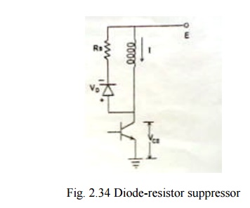
A high
resistance RS is required to achieve a quick current decay, but this also
results in a higher collector potential VCE, thus a transistor with a high
maximum voltage rating is necessary.
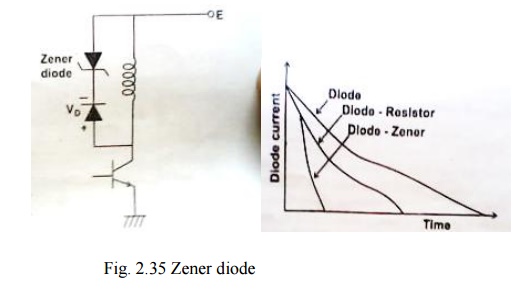
(a) Zener diode suppressor
In this
zener diode are often used to connect in series with the ordinary diode as
shown in fig. Compared with preceding two cases zener diode which provides
negative bias causes the current to decay more quickly after turn off. In
addition to this, it is a merit of this method that the potential applied to
the collector is the supply potential plus the zener potential, independent of
the current. This makes the determination of the rating of the maximum
collector potential easy. However zeners are signal diodes, rather than power
diodes. Their power dissipation is limited to 5w. Consequently, this suppressor
can be used for very small instrument stepper motors of typical size 8 to 11.
Comparison
of effects of various suppressor schemes of various suppressor schemes
(d)Condenser suppressor
This scheme is often employed for bifilar-wound hybrid motor. An explanation is given for the given for the circuit shown in fig:
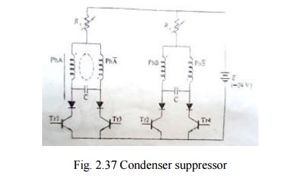
A
condenser is put between ph A and ph A1. These condensers serve two fold
purposes.
1. When a
transistor is turned off, the condenser connected to it via a diode absorbs the
decaying current from the winding to protect the transistor.
Let us
see the situation just after the Tr 1 is turned off in the one phase on mode.
Either Tr2 or Tr4 will turn on, but Tr3 will still be in the turned off state .
Since the winding of ph A and ph A1 are wound in the bifilar fashion, a
transient current will circulate in loop. If Tr 3 is turned on when the
transient current becomes zero and the charge stored in the condenser becomes
maximum, a positive current can easily flow through phase A winding. By this
resonance mechanism, currents are used efficiently in this scheme. This feature
remains in the two phase on mode too. The condenser suppressor is suited to
drives in which stepping rate is limited in a narrow range.
2
.Another utility of condensers is as an electrical damper, a method of damping
rotor oscillations is to provide a mechanism to convert kinetic energy to joule
heating. If a rotor having a permanent magnet oscillates, an alternating emf is
generated in the winding. However if a current path is not provided or a high
resistance is connected, no current will be caused by this emf. When the
condenser is connected between phases an oscillatory current will flow in the
closed loop and joule heat is generated in the windings, which means that the
condenser works as an electrical damper.
Related Topics