Chapter: Optical Communication and Networking : Transmission Characteristics of Optical Fiber
Dispersion
Dispersion
Dispersion
of the transmitted optical signal causes distortion for both digital and analog
transmission along optical fibers. When considering the major implementation of
optical fiber transmission which involves some form of digital modulation, then
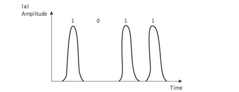
dispersion mechanisms within the fiber cause broadening of the transmitted
light pulses as they travel along the channel. The phenomenon is illustrated in
Figure 2.7, where it may be observed that each pulse broadens and overlaps with
its neighbors, eventually becoming indistinguishable at the receiver input. The
effect is known as intersymbol interference (ISI). Thus an increasing number of
errors may be encountered on the digital optical channel as the ISI becomes
more pronounced. The error rate is also a function of the signal attenuation on
the link and the subsequent signal-to-noise ratio (SNR) at the receiver.
For no
overlapping of light pulses down on an optical fiber link the digital bit rate BT must be less than the reciprocal of
the broadened (through dispersion) pulse duration (2t).
Hence:
The
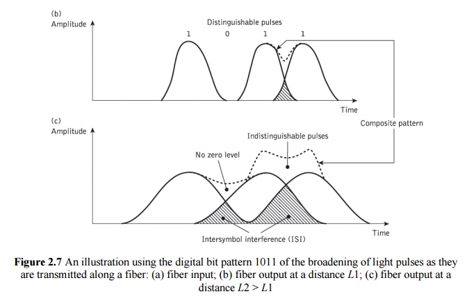
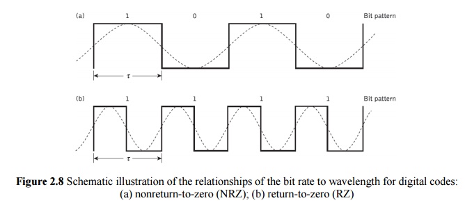
conversion of bit rate to bandwidth in hertz depends on the digital coding
format used. For metallic conductors when a nonreturn-to-zero code is employed,
the binary 1 level is held for the whole bit period τ. In this case there are
two bit periods in one wavelength (i.e. 2 bits per second per hertz), as
illustrated in Figure 2.8(a). Hence the maximum bandwidth B is one-half the maximum data rate or:

However,
when a return-to-zero code is considered, as shown in Figure 2.8(b), the binary
1 level is held for only part (usually half ) of the bit period. For this
signaling scheme the data rate is equal to the bandwidth in hertz (i.e. 1 bit
per second per hertz) and thus BT = B.
The
bandwidth B for metallic conductors
is also usually defined by the electrical 3 Db points (i.e. the frequencies at
which the electric power has dropped to one-half of its constant maximum
value). However, when the 3 dB optical bandwidth of a fiber is considered it is
significantly larger than the corresponding 3 dB electrical bandwidth. Hence,
when the limitations in the bandwidth of a fiber due to dispersion are stated
(i.e. optical bandwidth Bopt), it is
usually with regard to a return to zero code where the bandwidth in hertz is
considered equal to the digital bit rate. Within the context of dispersion the
bandwidths expressed in this chapter will follow this general criterion unless
otherwise stated.
when
electro-optic devices and optical fiber systems are considered it is more usual
to statethe electrical 3 dB bandwidth, this being the more useful measurement
when interfacing an optical fiber link to electrical terminal equipment.
Related Topics