Chapter: Protection and Switchgear : Operating Principles and Relay Characteristics
Differential Relay
Differential Relay
One of the most prevalent and successful method of protecting a circuit is to arrange relays to compare the currents entering and leaving it, which should be the same under normal conditions and during an external fault. Any difference current must be flowing in to a fault within the protected circuit
Principle of circulating current differential (MERZ-PRIZE) protection
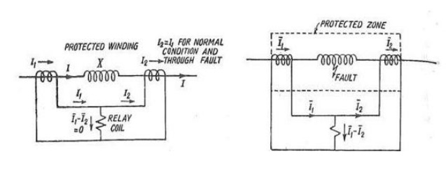
The figure below illustrates the principle of differential protection of generator and transformer, X is the winding of the protected machine. Where there is no internal fault, the current entering in X is equal in phase and magnitude to current leaving X. The CT's have such a ratio that during the normal conditions or for external faults (Through Faults) the secondary current of CT's are equal. These current say I1 and I2 circulate in the pilot wire. The polarity connections are such the current I1 and I2 are in the same direction of pilot wire during normal condition or external faults. Relay operation coil is connected at the middle of pilot wires. Relay unit is of over current type

During normal condition and external fault the protection system is balanced and the CT's ratios are such that secondary currents are equal. These current circulate in pilot wires. The vector differential current I1- I2 which flow through the relay coil is zero. I1-I2 = 0 (normal condition or external faults) This balance is disturbed for internal faults. When fault occurs in the protected zone, the current entering the protected winding is no more equal to the leaving the winding because some current flows to the fault. The differential I1-I2 flows through the relay operating coil and the relay operates if the operating torque is more than the restraining torque. The current I1 and I2 circulate in the secondary circuit. Hence CT's does not get damaged. Polarities of CT's should be proper, otherwise the currents I1 and I2 would add up even for normal condition and mal operate the relay.
Differential Protection current balance
• When this system is applied to electrical equipment (Generator stator windings, Transformer,
Bus bars etc.) it is called differential current protection.
• When it is applied to lines and cables it is called pilot differential protection because pilot wires or an equivalent link or channel is required to bring the current to the relay from the remote end of the line.
The CTs at both ends of the protected circuit connected so that for through load or through fault conditions current circulates between the interconnected CTs. The over-current relay is normally connected across equipotential points and therefore doesn‟t operate.
• Circulating current balance methods are widely used for apparatus protection where CTs are within the same substation area and interconnecting leads between CTs are short (e.g. generator stator windings, Transformer, Bus bars etc.)
• The circulating current balance method is also called longitudinal differential protection or
Merz-Price differential protection system.
• The current in the differential relay would be proportional to the phasor difference between the currents that enter and leave the protected circuit. If the current through the relay exceeds the pick-up value, then the relay will operate.
Demerits of a Differential Relay( Merz Price Scheme)
· Unmatched characteristics of C.T.s :
Though the saturation is avoided, there exist difference in the C.T. characteristics due to ratio error at high values of short circuit currents. This causes an appreciable difference in the secondary currents which can operate the relay. So the relay operates for through external faults.
This difficulty is overcome by using percentage differential relay. In this relay, the difference in current due to the ratio error exists and flows through relay coil. But at the same time the average current ( I1 + I2/2) flows through the restraining coil which produces enough restraining torque. Hence relay becomes inoperative for the through faults.
· Ratio change due to tap change:
To alter the voltage and current ratios between high voltage and low voltage sides of a power transformer, a tap changing equipment is used. This is an important feature of a power transformer. This equipment effectively alters the turns ratio. This causes unbalance on both sides. To compensate for this effect, the tapping can be provided on C.T.s also which are to be varied similar to the main power transformer. But this method is not practicable. The percentage differential relays ensure relays ensure the stability with respect to the amount of unbalance occurring at the extremities of the tap change range.
· Difference in lengths of pilot wires:
Due to the difference in lengths of the pilot wires on both sides, the unbalance condition may result. The difficulty is overcome by connecting the adjustable resistors in pilot wires on both sides. These are called balancing resistors. With the help of these resistors, equipotential points on the pilot wires can be adjusted. In percentage differential relays the taps are provided on the operating coil and restraining coil to achieve an accurate balance.
· Magnetizing current inrush:
When the transformer is energized, the condition initially is of zero induced E.m.f. A transient inflow of magnetizing current occurs in to the transformer. This current is called magnetizing inrush current. This current may be as great as 10 times the full load current of the transformer. This decays very slowly and is bound to operate differential protection of the transformer falsely, because of the temporary difference in magnitude of the primary and secondary currents.
The factors which affect the magnitude and direction of the magnetizing inrush current can be one of the following reasons.
a. Size of the transformer.
b. Size of the power system
c. Type of magnetic material used for the core.
d. The amount of residual flux existing before energizing the transformer.
e. The method by which transformer is energized.
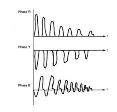
If the transformer is energized when the voltage wave is passing through zero, the magnetizing current inrush is maximum. At this instant, the current and flux should be maximum in highly inductive circuit. And in a half wave flux reversal must take place to attain maximum value in the other half cycles. If the residual flux exists, the required flux may be in same or opposite direction. Due to this magnetizing current inrush is less or more. If it is more, it is responsible to saturate the core which further increases its component. This current decays rapidly for first few cycles and then decays slowly. The time constant L/R of the circuit is variable as inductance of circuit varies due to the change in permeability of the core. The losses in the circuit damp the inrush currents. Depending on the size of the transformer, the time constant of inrush current varies from 0.2 sec to 1 sec. The waveforms of magnetizing inrush current in three phases are shown in the figure below.
Related Topics