Chapter: Power Quality : Harmonics
Devices for Controlling Harmonic Distortion
Devices for Controlling Harmonic Distortion
There are a number of devices available to control harmonic distortion. They can be as simple as a capacitor bank or a line reactor, or as complex as an active filter.
1. PASSIVE FILTERS:
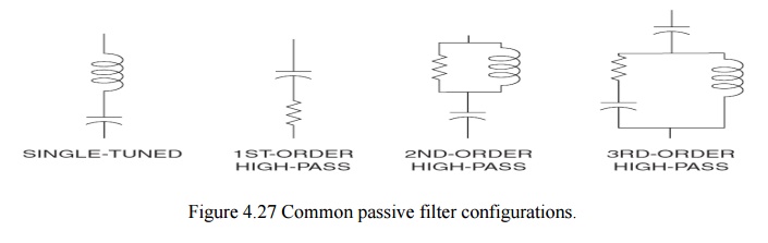
Passive filters are inductance, capacitance, and resistance elements configured and tuned to control harmonics. They are commonly used and are relatively inexpensive compared with other means for eliminating harmonic distortion. However, they have the disadvantage of potentially interacting adversely with the power system, and it is important to check all possible system interactions when they are designed. They are employed either to shunt the harmonic currents off the line or to block their flow between parts of the system by tuning the elements to create a resonance at a selected frequency. Figure 4.27 shows several types of common filter arrangements.
2. SHUNT PASSIVE FILTERS:
The most common type of passive filter is the single tuned “notch” filter. This is the most economical type and is frequently sufficient for the application. The notch filter is series-tuned to present low impedance to a particular harmonic current and is connected in shunt with the power system. Thus, harmonic currents are diverted from their normal flow path on the line through the filter. Notch filters can provide power factor correction in addition to harmonic suppression. In fact, power factor correction capacitors may be used to make notch filters. The dry-type iron-core reactor is positioned atop the capacitors, which are connected in a wye, or star, configuration with the other phases (not shown). Each capacitor can is fused with a current-limiting fuse to minimize damage in case of a can failure. In outdoor installations it is often more economical to use air-core reactors.
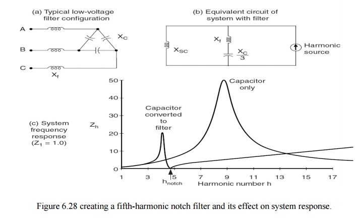
Iron-core reactors may also be oil-insulated. Here the reactors are placed on top of the cabinet housing the capacitors and switchgear. An example of a common 480-V filter arrangement is illustrated in Fig. 4.28. The figure shows a delta-connected low-voltage capacitor bank converted into a filter by adding an inductance in series with the phases. In this case, the notch harmonic h notch is related to the fundamental frequency reactances by
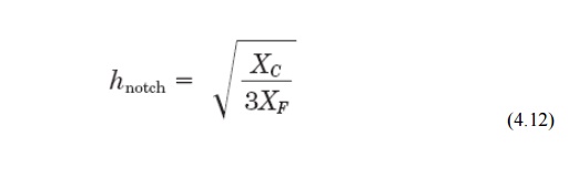
Note that XC in this case is the reactance of one leg of the delta rather than the equivalent line-to-neutral capacitive reactance.
3. SERIES PASSIVE FILTERS:
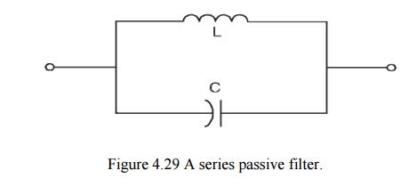
Unlike a notch filter which is connected in shunt with the power system, a series passive filter is connected in series with the load. The inductance and capacitance are connected in parallel and are tuned to provide high impedance at a selected harmonic frequency. The high impedance then blocks the flow of harmonic currents at the tuned frequency only. At fundamental frequency, the filter would be designed to yield low impedance, thereby allowing the fundamental current to follow with only minor additional impedance and losses. Fig 4.29. Shows a typical series filter arrangement. Series filters are used to block a single harmonic current (such as the third harmonic) and are especially useful in a single-phase circuit where it is not possible to take advantage of zero-sequence characteristics. The use of the series filters is limited in blocking multiple harmonic currents. Each harmonic current requires a series filter tuned to that harmonic. This arrangement can create significant losses at the fundamental frequency.
4. LOW-PASS BROADBAND FILTERS:
Multiple stages of both series and shunt filters are often required in practical applications. For example, in shunt filter applications, a filter for blocking a seventh-harmonic frequency would typically require two stages of shunt filters, the seventh-harmonic filter itself and the lower fifth-harmonic filter. Similarly, in series filter applications, each frequency requires a series filter of its own; thus, multiple stages of filters are needed to block multiple frequencies. In numerous power system conditions, harmonics can appear not only in a single frequency but can spread over a wide range of frequencies. A six-pulse converter generates characteristic harmonics of 5th, 7th, 11th, 13th, etc. Electronic powers converters can essentially generate time-varying inter harmonics covering a wide range of frequencies.
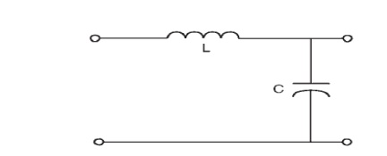
Designing a shunt or series filter to eliminate or reduce these widespread and time-varying harmonics would be very difficult using shunt filters. Therefore, an alternative harmonic filter must be devised. A low-pass broadband filter is an ideal application to block multiple or widespread harmonic frequencies. Current with frequency components below the filter cutoff frequency can pass; however, current with frequency components above the cutoff frequency is filtered out. Since this type of low-pass filter is typically designed to achieve a low cutoff frequency, it is then called a low-pass broadband filter. A typical configuration of a low-pass broadband filter is shown in Fig. 4.30.
5. C FILTERS:
C filters are an alternative to low-pass broadband filters in reducing multiple harmonic frequencies simultaneously in industrial and utility systems. They can attenuate a wide range of steady state and time-varying harmonic and inter harmonic frequencies generated by electronic converters, induction furnaces, cyclo converters, and the like.
6. ACTIVE FILTERS:
Active filters are relatively new types of devices for eliminating harmonics. They are based on sophisticated power electronics and are much more expensive than passive filters. However, they have the distinct advantage that they do not resonate with the system. Active filters can work independently of the system impedance characteristics. Thus, they can be used in very difficult circumstances where passive filters cannot operate successfully because of parallel resonance problems. They can also address more than one harmonic at a time and combat other power quality problems such as flicker. They are particularly useful for large, distorting loads fed from relatively weak points on the power system.
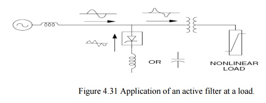
The basic idea is to replace the portion of the sine wave that is missing in the current in a nonlinear load. Figure 4.31 illustrates the concept. An electronic control monitors the line voltage and/or current, switching the power electronics very precisely to track the load current or voltage and force it to be sinusoidal. As shown, there are two fundamental approaches: one that uses an inductor to store current to be injected into the system at the appropriate instant and one that uses a capacitor. Therefore, while the load current is distorted to the extent demanded by the nonlinear load, the current seen by the system is much more sinusoidal.
Related Topics