Chapter: Embedded Systems
Devices and Buses for Devices Network
DEVICES AND BUSES FOR DEVICES NETWORK
I/O Devices - Device I/O Types and Examples – Synchronous - Iso-synchronous and Asynchronous Communications from Serial Devices - Examples of Internal Serial-Communication Devices - UART and HDLC - Parallel Port Devices - Sophisticated interfacing features in Devices/Ports- Timer and Counting Devices -
IO port types- Serial and parallel IO ports
A port is a device to receive the bytes from external peripheral(s) [or device(s) or processor(s) or controllers] for reading them later using instructions executed on the processor to send the bytes to external peripheral or device or processor using instructions executed on processor.
A Port connects to the processor using address decoder and system buses. The processor uses the addresses of the port-registers for programming the port functions or modes, reading port status and for writing or reading bytes.
Example
· SI serial interface in 8051
· SPI serial peripheral interface in 68HC11
· PPI parallel peripheral interface 8255
· Ports P0, P1, P2 and P3 in 8051 or PA, PB,PC and PD in 68HC11
· COM1 and COM2 ports in an IBM PC
IO Port Types
Types of Serial ports
· Synchronous Serial Input
· Synchronous Serial Output
· Asynchronous Serial UART input
· Asynchronous Serial UART output (both as input and as output, for example, modem.)
·
Types of parallel ports
· Parallel port one bit Input
· Parallel one bit output
· Parallel Port multi-bit Input
· Parallel Port multi-bit Output
Synchronous Serial Input Example
Inter-processor data transfer, reading from CD or hard disk, audio input, video input, dial tone, network input, transceiver input, scanner input, remote controller input, serial I/O bus input, writing to flash memory using SDIO (Secure Data Association IO based card).
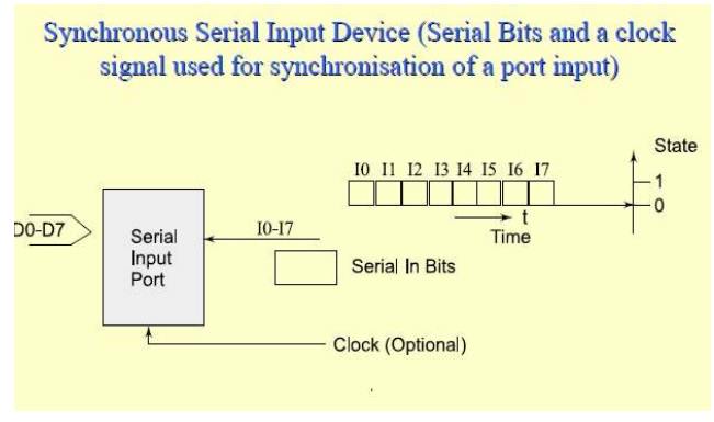
Synchronous Serial Input
· The sender along with the serial bits also sends the clock pulses SCLK (serial clock) to the receiver port pin. The port synchronizes the serial data input bits with clock bits. Each bit in each byte as well as each byte in synchronization
· Synchronization means separation by a constant interval or phase difference. If clock period = T, then each byte at the port is received at input in period = 8T.
· The bytes are received at constant rates. Each byte at input port separates by 8T and data transfer rate or the serial line bits is (1/T) bps. [1bps = 1 bit per s]
· Serial data and clock pulse-inputs
· On same input line − when clock pulses either encode or modulate serial data input bits suitably. Receiver detects the clock pulses and receives data bits after decoding or demodulating.
On separate input line − When a separate SCLK input is sent, the receiver detects at the middle or+ ve edge or –ve edge of the clock pulses that whether the data-input is 1 or 0 and saves the bits in an 8-bit shift register. The processing element at the port (peripheral) saves the byte at a port register from where the microprocessor reads the byte.
Master output slave input (MOSI) and Master input slave output (MISO)
MOSI when the SCLK is sent from the sender to the receiver and slave is forced to synchronize sent inputs from the master as per the inputs from master clock.
· MISO when the SCLK is sent to the sender (slave)from the receiver (master) and slave is forced to synchronize for sending the inputs to master as per the master clock outputs.
· Synchronous serial input is used for inter processor transfers, audio inputs and streaming data inputs.
Example Synchronous Serial Output
Inter-processor data transfer, multiprocessor communication, writing to CD or hard disk, audio Input/output, video Input/output,dialer output, network device output, remote TV Control, transceiver output, and serial I/O bus output or writing to flash memory using SDIO
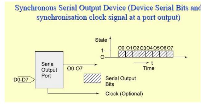
Synchronous Serial Output
· Each bit in each byte sent in synchronization with a clock.
· Bytes sent at constant rates. If clock period= T, then data transfer rate is (1/T) bps.
· Sender either sends the clock pulses at SCLK pin or sends the serial data output and clock pulse-input through same output line with clock pulses either suitably modulate or encode the serial output bits.
Synchronous serial output using shift register
· The processing element at the port (peripheral) sends the byte through a shift register at the port to where the microprocessor writes the byte.
· Synchronous serial output is used for inter processor transfers, audio outputs and streaming data outputs.
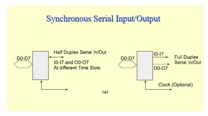
Synchronous Serial Input/output
· Each bit in each byte is in synchronization at input and each bit in each byte is in synchronization at output with the master clock output.
· The bytes are sent or received at constant rates. The I/Os can also be on same I/O line when input/output clock pulses either suitably modulate or encode the serial input/output, respectively. If clock period = T, then data transfer rate is (1/T)bps.
· The processing element at the port (peripheral)sends and receives the byte at a port register to or from where the microprocessor writes or reads the byte
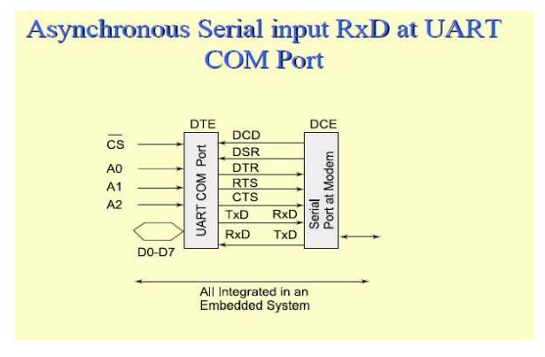
Asynchronous Serial port line RxD (receive data).
· Does not receive the clock pulses or clock information along with the bits.
· Each bit is received in each byte at fixed intervals but each received byte is not in synchronization.
· Bytes separate by the variable intervals or phase differences.
· Asynchronous serial input also called UART input if serial input is according to UART protocol
Example Serial Asynchronous Input
· Asynchronous serial input is used for keypad inputs and modem inputs in computers
· Keypad controller serial data-in, mice, keyboard controller, modem input, character send inputs on serial line [also called UART (universal receiver and transmitter) input when according to UART mode]
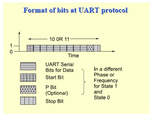
UART protocol serial line format
· Starting point of receiving the bits for each byte is indicated by a line transition from 1to 0 for a period = T. [T−1 called baud rate.]
· If sender‘s shift-clock period = T, then a byte at the port is received at input in period= 10.T or 11.T due to use of additional bits at start and end of each byte. Receiver detects n bits at the intervals of T from the middle of the start indicating bit. The n = 0, 1, …, 10 or 11 and finds whether the data-input is 1 or 0 and saves the bits in an 8-bit shift register.
· Processing element at the port (peripheral)saves the byte at a port register from where the microprocessor reads the byte.
Asynchronous Serial Output
· Asynchronous output serial port line TxD(transmit data).
· Each bit in each byte transmit at fixed intervals but each output byte is not in synchronization (separates by a variable interval or phase difference). Minimum separation is 1 stop bit interval TxD.
· Does not send the clock pulses along with the bits.
· Sender transmits the bytes at the minimum intervals of n.T. Bits receiving starts from the middle of the start indicating bit,
· n = 0, 1, …, 10 or 11 and sender sends the bits through a 10 or 11 -bit shift register.
The processing element at the port(peripheral) sends the byte at a port register to where the microprocessor is to write the byte.
· Synchronous serial output is also called UART output if serial output is according to
UART protocol
Example Serial Asynchronous Output
_ Output from modem, output for printer, the output on a serial line [also called UART output
when according to UART]
Half Duplex
· Half duplex means as follows: at an instant communication can only be one way (input or output) on a bi-directional line.
· An example of half-duplex mode─ telephone communication. On one telephone line, the talk can only in the half duplex way mode.
Full Duplex
· Full duplex means that at an instant, the communication can be both ways.
An example of the full duplex asynchronous mode of communication is the communication between the modem and the computer though TxD and RxD lines or communication using
SI in modes 1, 2 and 3 in 8051
Parallel Port single bit input
· Completion of a revolution of a wheel,
· Achievingpreset pressure in a boiler,
· Exceeding the upper limit of permitted weight over the pan of an electronic balance,
· Presence of a magnetic piece in the vicinity of or within reach of a robot arm to its endpoint and Filling of a liquid up to a fixed level.
Parallel Port Output- single bit
· PWM output for a DAC, which controls liquid level, or temperature, or pressure, or speed or angular position of a rotating shaft or a linear displacement of an object or a D.C. motor control
· Pulses to an external circuit
· Control signal to an external circuit
Parallel Port Input- multi-bit
· ADC input from liquid level measuring sensor or temperature sensor or pressure sensor or speed sensor or d.c. motor rpm sensor
· Encoder inputs for bits for angular position of a rotating shaft or a linear displacement of an object.
Parallel Port Output- multi-bit
· LCD controller for Multilane LCD display matrix unit in a cellular phone to display on the screen the phone number, time, messages, character outputs or pictogrambit-images for display screen or e-mail or web page
· Print controller output
· Stepper-motor coil driving bits
Parallel Port Input-Output
· PPI 8255
· Touch screen in mobile phone
Ports or Devices Communication and communication protocols
Two Modes of communication between the devices and computer system
Full Duplex – Both devices or device and computer system simultaneously communicate each
other.
Half Duplex – Only one device can communicate with another at an instance Three ways of communication between the ports or devices
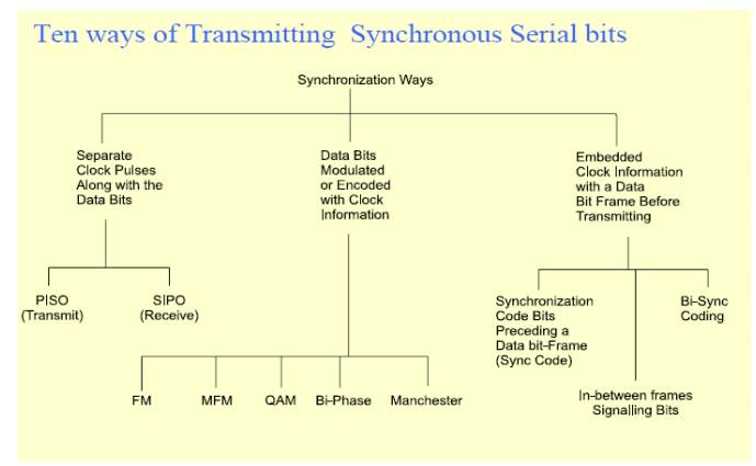
1. Synchronous
2. Iso-synchronous
3. Asynchronous
1. Synchronous and Iso-synchronous Communication in Serial Ports or Devices Synchronous
Communication.
When a byte (character) or a frame (a collection of bytes) in of the data is received or transmitted at the constant time intervals with uniform phase differences, the communication is called as synchronous. Bits of a full frame are sent in a prefixed maximum time interval.
Iso-synchronous
Synchronous communication special case−when bits of a full frame are sent in themaximum time interval, which can be variable.
Synchronous Communication
Clock information is transmitted explicitly or implicitly insynchronous communication. The receiver clock continuously maintains constant phase difference with the transmitter clock. Bits of a data frame maintain uniform phase difference and are sent within a fixed maximum time interval.
Example of synchronous serial communication
· Frames sent over a LAN. Frames of data communicate with the constant time intervals between each frame remaining constant.
· Another example is the inter-processor communication in a multiprocessor system Optional Synchronous Code bits
· Optional Sync Code bits or bi-sync code bits or frame start and end signaling bits─
During communication few bits (each separated by interval ΔT) sent as Sync code to enable the frame synchronization or frame start signaling.
· Code bits precede the data bits.
· May be inversion of code bits after each frame in certain protocols.
· Flag bits at start and end are also used in certain protocols. Always present Synchronous device port data bits
· Reciprocal of T is the bit per second(bps).
· Data bits─ m frame bits or 8 bits transmit such that each bit is at the line for time ΔT or, each frame is at the line for time (m. T)m may be 8 or a large number. It depends on the protocol Synchronous device clock bits
· Clock bits ─ Either on a separate clock line or on data line such that the clock information is also embedded with the data bits by an appropriate encoding or modulation
· Generally not optional
First characteristics of synchronous communication
1. Bytes (or frames) maintain a constant phase difference, which means they are synchronous, i.e. in synchronization. No permission of sending either the bytes or the frames at the random time intervals, this mode therefore does not provide for handshaking during the communication interval ─ This facilitates fast data communication at pre-fixed bps. Second characteristics of synchronous communication
2. A clock ticking at a certain rate has always to be there for transmitting serially the bits of all the bytes (or frames) serially. Mostly, the clock is not always implicit to the synchronous data receiver. The transmitter generally transmits the clock rate information
Asynchronous Communication from Serial Ports or Devices
Asynchronous Communication Clocks of the receiver and transmitter independent, unsynchronized, but of same frequency and variable phase differences between bytes or bits of two data frames, which may not be sent within any prefixed time interval.
Example of asynchronous communication
• UART Serial, Telephone or modem communication.
• RS232C communication between the UART devices
• Each successive byte can have variable time-gap but have a minimum in-between interval and no maximum limit for full frame of many bytes
Two characteristics of asynchronous communication
1. Bytes (or frames) need not maintain a constant phase difference and are asynchronous, i.e., not in synchronization. There is permission to send either bytes or frames at variable time intervals─ This facilitates in-between handshaking between the serial transmitter port and serial receiver port
2. Though the clock must ticking at a certain rate always has to be there to transmit the bits of a single byte (or frame) serially, it is always implicit to the asynchronous data receiver and is independent of the transmitter
Clock Features
_ The transmitter does not transmit (neither separately nor by encoding using modulation)along with the serial stream of bits any clock rate information in the asynchronous communication and receiver clock thus is notable to maintain identical frequency and constant phase difference with transmitter clock
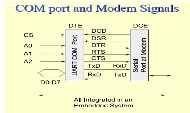
Example: IBM personal computer has two COM ports (communication ports)
· _ COM1 and COM2 at IO addresses 0x2F8-0xFFand 0xx38-0x3FF
· _ Handshaking signals─ RI, DCD, DSR, DTR,RTS, CTS, DTR
· _ Data Bits─ RxD and TxD Example: COM port and Modem Handshaking signals
· _ When a modem connects, modem sends data carrier detect DCD signal at an instance t0.
· _ Communicates data set ready (DSR)signal at an instance t1 when it receives the bytes on the line.
· _ Receiving computer (terminal) responds at an instance t2 by data terminal
ready(DTR) signal.
After DTR, request to send (RTS) signal is sent at an instance t3
· _ Receiving end responds by clear to send (CTS) signal at an instance t4. After the response CTS, the data bits are transmitted by modem from an instance t5 to the receiver terminal.
· _ Between two sets of bytes sent in asynchronous mode, the handshaking signals RTS and CTS can again be exchanged. This explains why the bytes do not remain synchronized during asynchronous transmission.
3. Communication Protocols
1. Protocol
A protocol is a standard adopted, which tells the way in which the bits ofa frame must be sent from a device (or controller or port or processor) to another device or system
[Even in personal communication we follow a protocol – we say Hello! Then talk and then say good bye!]
A protocol defines how are the frame bits:
1) sent− synchronously or Isosynchronouslyor asynchronously and at what rate(s)?
2)preceded by the header bits? How the receiving device address communicated so that only destined device activates and receives the bits?
[Needed when several devices addressed though a common line(bus)]
3)How can the transmitting device address defined so that receiving device comes to know the source when receiving data from several sources?
4) How the frame-length defined so that receiving device know the frame-size in advance?
5) Frame-content specifications –Are the sent frame bits specify the control or device configuring or commend or data?
6) Are there succeeding to frame the trailing bits so that receiving device can check the errors, if any in reception before it detects end of the frame ?
A protocol may also define:
Frame bits minimum and maximum length permitted per frame
8) Line supply and impedances and line-Connectors specifications
Specified protocol at an embedded system port or communication device IO port bits sent after first formatted according to a specified protocol, which is to be followed when communicating with another device through an IO port or channel
Protocols
· _ HDLC, Frame Relay, for synchronous communication
· _ For asynchronous transmission from a device port− RS232C, UART, X.25, ATM, DSL
and
ADSL
· _ For networking the physical devices in telecommunication and computer networks −
Ethernet and token ring protocols used in LAN Networks
Protocols in embedded network devices
o _ For Bridges and routers
o _ Internet appliances application protocols and Web protocols ─HTTP (hyper text transfer protocol), HTTPS (hyper text transfer protocol Secure Socket Layer),SMTP (Simple Mail Transfer Protocol),POP3 (Post office Protocol version 3),ESMTP (Extended SMTP),
File transfer, Boot Protocols in embedded devices network
o _ TELNET (Tele network),
o _ FTP (file transfer protocol),
o _ DNS (domain network server),
o _ IMAP 4 (Internet Message Exchange Application Protocol) and
o _ Bootp (Bootstrap protocol).Wireless Protocols in embedded devices network
o _ Embedded wireless appliances uses wireless protocols─ WLAN 802.11,802.16, Bluetooth, ZigBee, WiFi, WiMax,
TIMING ANDCOUNTING DEVICES
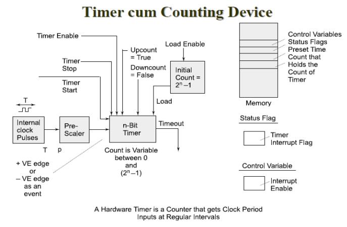
Timer
• Timer is a device, which counts the input at regular interval (δT) using clock pulses at its
input.
• The counts increment on each pulse and store in a register, called count register
• Output bits (in a count register or at the output pins) for the present counts.
Evaluation of Time
• The counts multiplied by the interval δT give the time.
• The (present counts −initial counts) × δT interval gives the time interval between two instances when present count bits are read and initial counts were read or set.
Timer
· _ Has an input pin (or a control bit in control register) for resetting it for all count bits = 0s.
· _ Has an output pin (or a status bit in status register) for output when all count bits = 0s after reaching the maximum value, which also means after timeout or overflow.
Counter
• A device, which counts the input due to the events at irregular or regular intervals.
• The counts gives the number of input events or pulses since it was last read.
• Has a register to enable read of present counts
• Functions as timer when counting regular interval clock pulses
_ Has an input pin (or a control bit in control register) for resetting it for all count bits = 0s. _ Has an output pin (or a status bit in status register) for output when all count bits = 0s after reaching the maximum value, which also means after timeout or overflow.
Timer or Counter Interrupt
_ When a timer or counter becomes 0x00or 0x0000 after 0xFF or 0xFFFF(maximum value), it can generate an ‘ interrupt‘, or an output ‗Time-Out‘ or set a status bit 'TOV‘
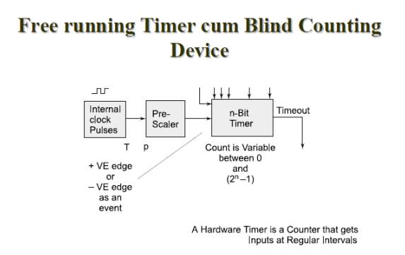
Free running Counter (Blind running Counter)
• A counting device may be a free running(blind counting) device giving overflow interrupts at fixed intervals
• A pre-scalar for the clock input pulses to fix the intervals
Free Running Counter
It is useful for action or initiating chain of actions, processor interrupts at the preset instances noting the instances of occurrences of the events
_ processor interrupts for requesting the processor to use the capturing of counts at the input instance
_ comparing of counts on the events for future Actions
Free running (blind counting) device Many Applications Based on
_ comparing the count (instance) with the one preloaded in a compare register[an additional register for defining an instance for an action]
_ capturing counts (instance) in an additional register on an input event.
[An addition input pin for sensing an event and saving the counts at the instance of event and taking action.]
Free running (Blind Counts) input OCenablepin (or a control bit in control register)
• For enabling an output when all count bits at free running count = preloaded counts in the compare register.
• At that instance a status bit or output pin also sets in and an interrupt ‗OCINT‘ of processor
can occur for event of comparison equality.
• Generates alarm or processor interrupts at the preset times or after preset interval
From another event
Free running (Blind Counts) input capture -enable pin (or a control bit in control register) for Instance of Event Capture
• A register for capturing the counts on an instance of an input (0 to 1 or 1 to 0or toggling) transition
_ A status bit can also sets in and processor interrupt can occur for the capture event
Free running (Blind Counts) Pre-scaling
• Prescalar can be programmed as p = 1, 2,4, 8, 16, 32, .. by programming a prescaler register.
•Prescalar divides the input pulses as per the programmed value of p.
• Count interval = p × δT interval
• δT = clock pulses period, clock frequency = δT −1
Free running (Blind Counts) Overflow
• It has an output pin (or a status bit in status register) for output when all count bits = 0s after reaching the maximum value, which also means after timeout or overflow
• Free running n-bit counter over flows after p × 2n × δT interval
Uses of a timer device
· _ Real Time Clock Ticks (System Heart Beats). [Real time clock is a clock,
which, once the system starts, does not stop and can't be reset and its count value can't be reloaded. Real timeendlessly flows and never returnsback!] Real Time Clock is set for ticks using pre-scaling bits (or rate set bits) inappropriate control registers.
· Initiating an event after a preset delay time. Delay is as per count value loaded.
· Initiating an event (or a pair of events or a chain of events) after a comparison(s) with between the pre-set time(s) with counted value(s). [It is similar to a preset alarm(s).].
· A preset time is loaded in a Compare Register. [It is similar to presetting an alarm].
· Capturing the count value at the timer on an event. The information of time(instance of the event) is thus stored at the capture register.
· Finding the time interval between two events. Counts are captured at each event in capture register(s) and read. The intervals are thus found out.
· Wait for a message from a queue or mailbox or semaphore for a preset time when using RTOS. There is a A predefined waiting period is done before RTOS lets a task run.
Watchdog timer.
It resets the system after a defined time.
· _ Baud or Bit Rate Control for serial communication on a line or network. Timer timeout interrupts define the time of each baud
· _ Input pulse counting when using a timer, which is ticked by giving non periodic inputs instead of the clock inputs. The timer acts as a counter if, in place of clock inputs, the inputs are given to the timer for each instance to be counted.
· _ Scheduling of various tasks. A chain of software-timers interrupt and RTOS uses these interrupts to schedule the tasks.
· _ Time slicing of various tasks. A multitasking or multi-programmed operating system presents the illusion that multiple tasks or programs are running simultaneously by switching between programs very rapidly, for example, after every 16.6 ms.
· _ Process known as a context switch.[RTOS switches after preset time-delay from one running task to the next. task. Each task can therefore run in predefined slots of time]
Time division multiplexing (TDM)
· _ Timer device used for multiplexing the input from a number of channels.
· _ Each channel input allotted a distinct and fixed-time slot to get a TDM output. [For example, multipletelephone calls are the inputs and TDM device generates the TDM output forlaunching it into the optical fiber.
Software Timer
_ A software, which executes and increases or decreases a count-variable(count value) on an interrupt from on a system timer output or from on a real time clock interrupt.
_ The software timer also generate interrupt on overflow of count-value or on finishing value of the count variable.
System clock
• In a system an hardware-timing device is programmed to tick at constant intervals.
• At each tick there is an interrupt
• A chain of interrupts thus occur at periodic intervals.
• The interval is as per a preset count value
• The interrupts are called system clock interrupts, when used to control the schedule sand timings of the system
Software timer (SWT)
• SWT is a timer based on the system clock interrupts
• The interrupt functions as a clock input to an SWT.
• This input is common to all the SWTs that are in the list of activated SWTs.
• Any number of SWTs can be made active in a list.
• Each SWT will set a status flag on its timeout (count-value reaching 0).
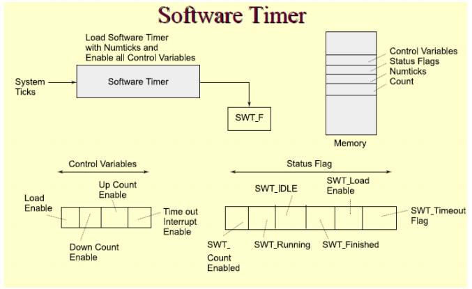
• Actions are analogous to that of a hardware timer. While there is physical limit (1, 2 or 3 or 4) for the number of hardware timers in a system, SWT scan be limited by the number of interrupt vectors provided by the user.
• Certain processors (microcontrollers)also defines the interrupt vector addresses of 2 or 4
SWTs
Related Topics