Chapter: Digital Electronics : Sequential Circuits
Design of Synchronous Counters
DESIGN OF SYNCHRONOUS COUNTERS:
This section begins our study of designing an important class of clocked sequential logic circuits-synchronous finite-state machines. Like all sequential circuits, a finite-state machine determines its outputs and its next state from its current inputs and current state. A synchronous finite state machine changes state only on the clocking event.
COUNTER DESIGN PROCEDURE:
Describe a general sequential circuit in terms of its basic parts and its input and outputs. Develop a state diagram for a given sequence. Develop a next-state table for a specific counter sequence. Create a FF transition table. Use K-map to derive the logic equations. Implement a counter to produce a specified sequence of states.
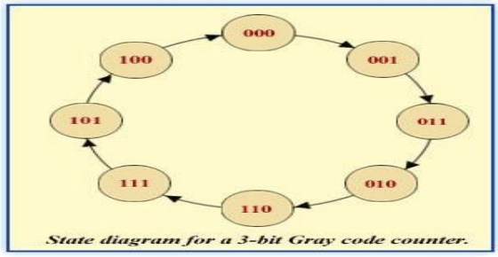
Design the 3-bit Gray code counter
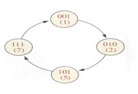
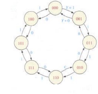
Step 1: State Diagram
State Diagram for a 3-bit Gray code counter:
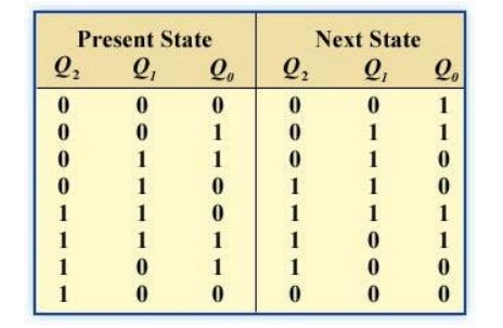
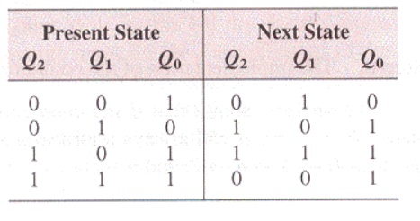
Step 2: Next-State Table
Next state table for a 3-bit Gray code counter
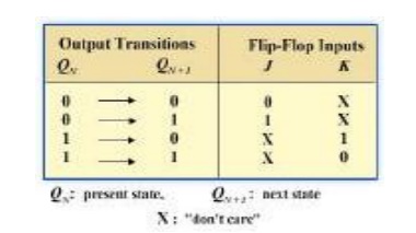
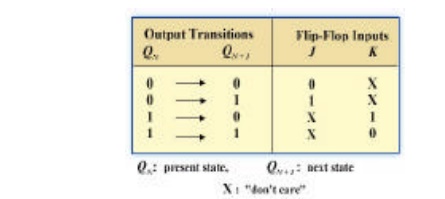
Step 3: Flip-Flop Transition Table
Transition table for a J-K Flip-Flop
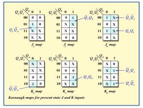
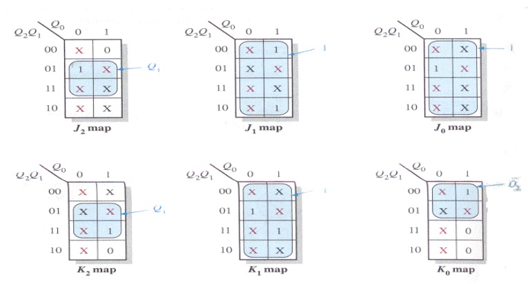
Step 4: Karnaugh Maps
The following diagram shows the steps to create separate next states of separate J and K from the current states of J and K.
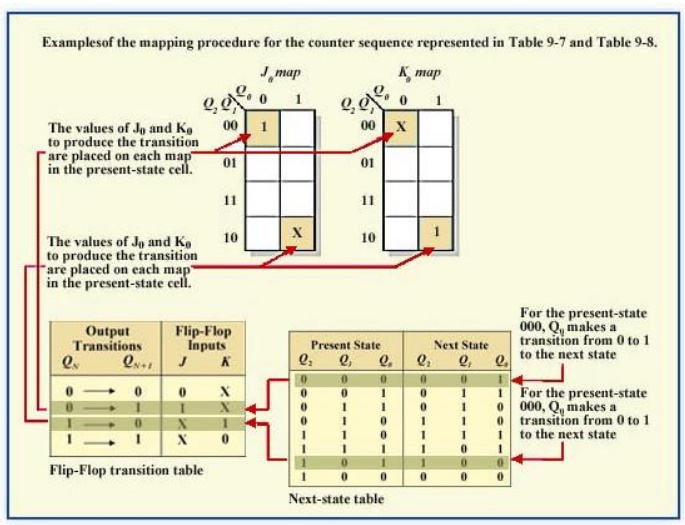
Karnaugh maps for present-state J and K inputs for the 3-bit Gray code counter..
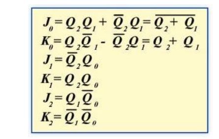
Step 5: Logic Expressions for Flip-flop Inputs
The next-state J and K outputs for a 3-bit Gray code counter.
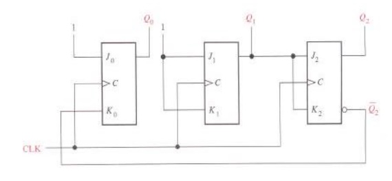
Step 6: Counter Implementation
The hardware diagram of the 3-bit Gray code counter
1. Design – Example 1
Design a counter with the irregular binary count sequence shown in the state diagram of Figure 4.1.
Step 1: State Diagram
Step 2: Next-State Table
Step 3: Flip-Flop Transition Table
Transition table for a J-K Flip-Flop
Step 4: Karnaugh Maps
Step 5: Logic Expressions for Flip-flop Inputs
The expression for each J and K input taken from the maps is as follows:
J0 = 1, K0 = Q2
J1 = K1 = 1
J2 = K2 = Q1
Step 6: Counter Implementation
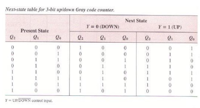
Example 2 - Design the 3 Up/down counter (Gray code sequence)
Step 1: State Diagram
Step 2: Next-State Table
Step 3: Flip-Flop Transition Table
Transition table for a J-K Flip-Flop
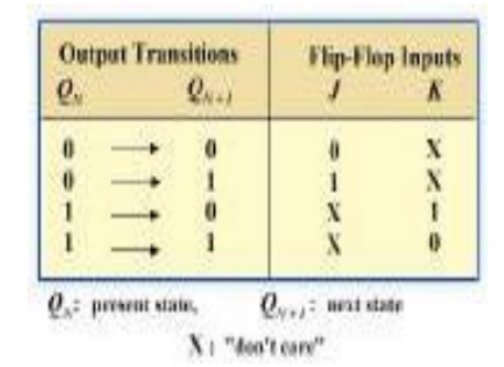
Here X denotes the don’t care condition Qn is the present state of transition output and
Qn+1 is the next state of the transition output
Step 4: Karnaugh Maps
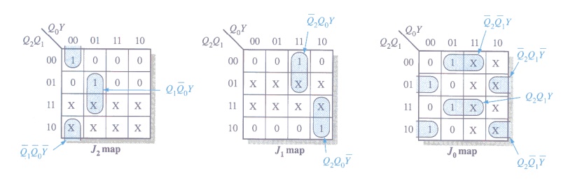
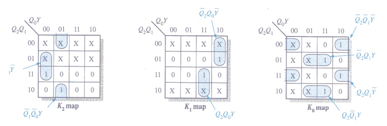
Step 5: Logic Expressions for Flip-flop Inputs
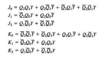
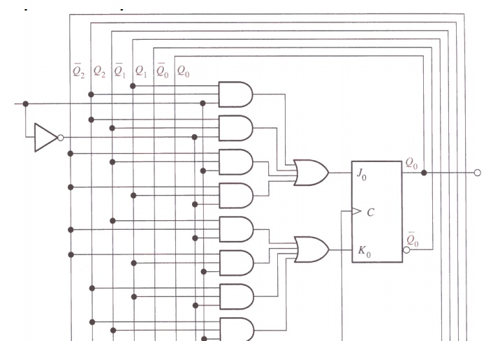
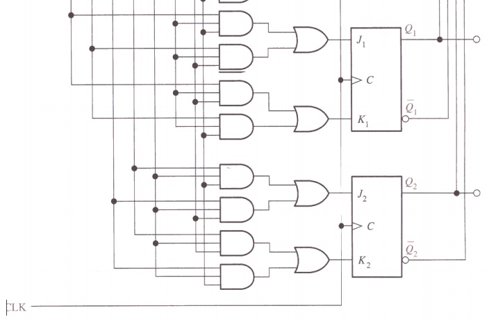
Step 6: Counter Implementation
Related Topics