Chapter: Aquaculture Principles and Practices: Design and Construction of Aquafarms
Design and construction of pond farms
Design and construction of pond farms
Considering that the construction of farm facilities forms the major capital investment in pond farms and that the operational efficiency of the facilities will largely determine the success of the project, it is fully justified and necessary to devote adequate attention to their design and construction. As mentioned earlier, pond farm designs are site-specific and so it is difficult to detail all possible variations. The aquaculturist will have to work closely with the design engineer to arrive at an economically acceptable design that will meet the operational requirements of the species and the culture technol-ogies. Planned construction is feasible in most projects, except when existing undrainable ponds, tanks or mining pits have to be used, as is the practice in some of the South Asian and Southeast Asian countries. Even then, it may often be possible to design a proper farm, incorporating the existing water bodies for easier management.
Size and shape
The size of a farm has to be determined on the basis of a number of factors, including quantity of water and extent of land available, technology to be followed (e.g. extensive, semi- intensive or intensive farming), production and income required to make the enterprise eco-nomically viable, and access to markets, man-power and equipment.
Even though the design of the farm will depend on several factors, there are some basic principles which are generally followed. Whether a hatchery is incorporated in the farm or not, there is usually a series of nursery ponds for growing larvae to fry stage, another series of rearing ponds to rear fry to the fingerling or yearling stage, and a final series of production or stock ponds. Many farms, particularly in tropical areas, may not have the transitional rearing ponds, and fry may be introduced directly into the stock or production ponds for grow-out to marketable size. In farms incorporating hatchery operations, there is a need for brood-stock ponds to rear selected brood-stock, and in some cases also spawning ponds. Depending on the harvesting system to be adopted, there may also be a need for market ponds for holding the harvests before marketing. Instead of earthen ponds, tanks or raceways may be used for fry rearing in certain types of culture, such as salmonids and shrimps. Tanks for culture of fry can very well be incorporated in the design of a pond farm, particularly in conjunction with a hatchery. Details of tank and raceway design will be discussed in a later section. In temperate and cold climates, winter-ing ponds or indoor wintering facilities may be needed.
It is possible to use some of the ponds mentioned above for more than one purpose, depending on the seasonality of operations. Spawning ponds can often be used for fry nursing after suitable preparation, and some-times also as market ponds. Properly designed rearing ponds can, after the fry season, be used as production ponds. Thus, economy can be effected in pond area and most of the ponds can be brought under operation for a major part of the year, if the farming technology permits it. Because of these possibilities, it will not be very meaningful to suggest a particular ratio between different types of ponds. The estimated number of fry required and the number of crops of fry that can be raised to meet the requirements of the farm will decide the total area to be assigned for nursery purposes. The production target of the farm, based on markets
and technology, will decide the area to be set apart for production ponds. For small-scale fish culture in tropical areas based on quick-growing species, it has been suggested that each farm should have a multiple of twelve production ponds, so that each month an equal number of ponds can be drained or harvested, ensuring a regular supply of fish for sale each month of the year (Maar et al., 1996).
The size of ponds would vary according to the intensity of culture operations, but ranges of 0.05–2.00 ha for nursery ponds and0.25–10.00 ha for production or stock ponds have been suggested. Spawning ponds could be 0.01 ha. Smaller ponds would result in a larger area covered by embankments and water supply channels. In intensive culture systems, there is an obvious preference for smaller ponds, ranging in size from 1 to 5 ha as against 3 to 10 ha in extensive systems, as small ponds allow greater control. Larger ponds take longer to fill or drain, under given water conditions. This may mean, in certain situations, sizeable loss of production time. Similarly, moderate-sized ponds facilitate safe harvesting, as too much crowding in harvesting sumps and handling can result in fish loss. It has been suggested that the harvesting of a pond should not take more than a day. This again points to the need for less extensive production ponds. However, it costs more per unit area to construct smaller ponds, because of the cost of the additional embankments and water supply structures needed.
There appears to be a greater preference for rectangular-shaped ponds in fresh-water farms. This is mainly to facilitate harvesting with seines of manageable length or through draining to a sump using the regular slope of the pond bottom. The lengths of drainage and feeder canals required will also be less. From the point of view of cost of construction, square-shaped ponds are considered preferable, as the ratio of water area to the length of embankment will be higher, but if the slope of the site selected is high it may be necessary to construct rectangular ponds, to enable easy drainage. In cases where fish culture is combined with animal production or cultivation of vegetables, fruit trees, etc., as in southern China, the cost of construction of the main embankments would not be a major consideration, as the farmers need wide land areas near theponds for animal or plant production. Many of the new farms there have square ponds, but others are rectangular in shape. Some East European countries, particularly Hungary, have tried different shapes of ponds, such as radial ponds, all of which drain into a central sump.
The layout of coastal pond farms is largely dependent on the farming procedures. Some of the typical layout designs will be described later, but there appears to be no special shape preference in newly designed ponds, though most of them are rectangular. The shape of the traditional farms largely follows the land contours and many of them have irregular shapes. In modern designs this is generally avoided and embankments are straight where possible.
Layout of farms
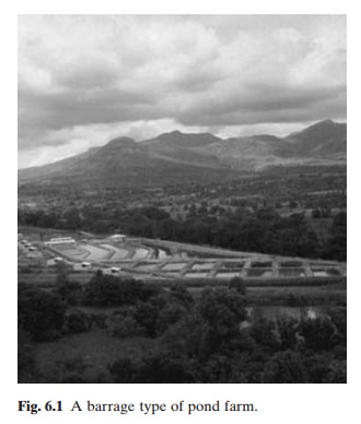
The conventional classification of fish pond design into barrage ponds, contour ponds and paddy ponds can still be used to describe the major types of pond layout. The barrage ponds are constructed in flat or gently sloping valleys, or abandoned river beds, by putting a low dam at a suitable site (fig. 6.1). The dam has to be built at the narrowest point to reduce construction costs. The sides of the ponds are formed by the slopes of the valley and a series of ponds can be built on the site. The source of water is a stream or river nearby. A spillway has to be built to avoid flooding of the ponds. A feeder canal from the stream will be necessary to regulate the water supply. Suitable drainage has to be provided to prevent flooding and consequent loss of stock and damage to the pond structures.
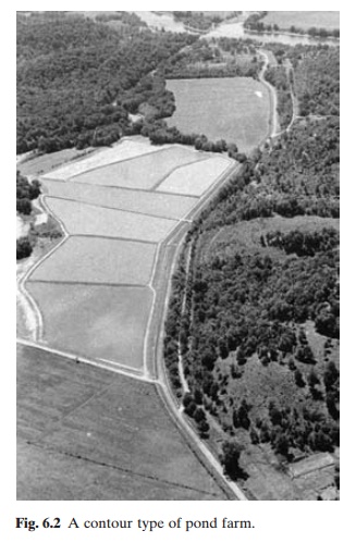
Contour ponds (fig. 6.2) are also generally located near a stream, canal, river or reservoir and in a valley, the bottom having a slightly sloping contour. The farm is situated on one side of the valley only and floods pass through the other side. A weir diverts the water for intake through a gate to a supply canal, from which each pond can be filled and drained separately. The dikes should be built to carry the design flood safely. Such a layout is possible only in sufficiently wide valleys or river beds.
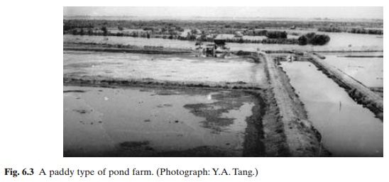
Paddy ponds (fig. 6.3) are constructed on relatively flat areas surrounded by a dike. Such sites make it possible to use much better layout designs, including separate supply and drainage channels, seepage and pond drains, harvestingsumps, etc. Most of the sites selected for carp, tilapia and catfish culture in fresh water and brackish water, or salt-water finfish and shrimps in coastal areas, would be suitable for this type of pond.
Dike design and construction
The most important constructions in a pond farm are the dike system and the water control structures. The pond bottoms may or maynot be excavated, depending on the topography and soil conditions, but the supply and drainage channels and harvesting pits have to be excavated.
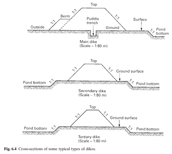
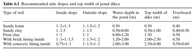
As indicated earlier, the constructional details of the dike will depend upon the nature of the soil to be used, water depth required in the ponds, wave action and possible erosion, etc. Fig. 6.4 illustrates cross-sections of some typical dikes. Since cost-efficiency is the major consideration, it is necessary to determine the steepest slope inclination of the dikes that will ensure stability of the structure on a long-term basis. Where the soil conditions warrant it, the economics of lining the dike slopes with bricks, rip-rap, wood, etc. should be determined, taking into account long-term maintenance costs and the security provided. The freeboard has to be determined according to wave action and design flood levels. Table 6.1 lists the recommended side slopes, top width and freeboard of dikes (Kovari, 1984b). It is recommended that small ponds be located, if topography permits,with their long axis parallel to the prevailing winds, in order to provide maximum aeration. Large ponds may have the long axis at right angles to the prevailing winds, as the winds blowing over a long stretch of water may create higher waves and greater erosion of the dike. A minimum of 3 m top width will be required for embankments to be used by vehicles, but when heavy vehicles are to be used, the main embankments may have to be as wide as 6 m. Adjustments may be needed if the design includes a water supply channel on the crest of the dike. Secondary and tertiary dikes can be narrower and lower, according to the water depth in the enclosed ponds.
The depth of water to be maintained in a pond depends very much on the climatic conditions and culture practices. The recommended depth of trout ponds is 1 m at the intake, sloping to 1.5 or 2 m at the outflow. A depth of about 1 m is preferred in tropical and subtropical carp culture ponds. Besides minimizing wide fluctuations of water temperature, this assists in reducing the growth of rooted aquatic weeds which are a major problem in fertilized ponds, particularly in the tropics. However, shallower ponds will be preferable during the growing period in temperate climates, to make use of the higher water temperature for enhanced production. Because of these differences, wide variations occur in the depth and sizes of different types of ponds in culture systems.A range of average water depth of 0.4–1.5 m for nursery ponds and 0.8–3.0 m for production or stocking ponds have been recorded. In fresh-water fish culture, spawning ponds may have an average depth of 0.4–1 m and holding or market ponds 1.2–2.0 m. The water area of nursery ponds varies between 0.05 and 2 ha and of production or stocking ponds between 0.25 and 10.0 ha. Spawning ponds are smaller, ranging from 0.01 to 0.5 ha and holding or market ponds from 0.10 to 1.0 ha.
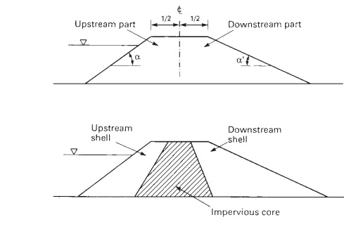
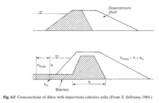
It is a common practice to provide an impervious core of soils of high cohesiveness, with shells of less cohesive soils on both sides or only on one side (fig. 6.5).The most important causes of deterioration of dike slopes are erosion due to wind and wave action and burrowing by aquatic animals, and the feeding habits of fish such as carp that rout around pond dikes. A proper grass cover is necessary to protect the exposed parts of the dike. Quick-growing and spreading varieties of grass are preferred. In East European ponds, a 4 m wide reed belt is recommended for larger stocking ponds (greater than 10 ha) to protect the sections of the dike exposed to wave action. In farms else-where, rip-rap placed in thicknesses of 0.25 to 0.5 m is preferred. In countries like China, blocks of concrete or bricks are used to line the slope. Lime stabilization has also been suggested as a means to improve soil compaction in dikes in order to resist erosive action.
The general principles of design and construction are very similar for fresh-water and coastal pond farms. However, the nature of the terrain and dependence on tidal water, as well as the practice of utillizing benthic algal pastures as food for the cultivated stock, necessitate some changes in the details of design and construction. The type of soil found in tidal areas selected for coastal farms has already been described. The construction of large embankments and heavy concrete structures on soft ground creates special problems. The fibrous or peaty top soil in man-grove areas (with roots sometimes constituting more than 50 per cent of the soil) is an additional problem. The need for, and methods of, easy drainage to leach out the acid contents of catclay soils have already been discussed. A system of open canals along the natural water-ways will be required for this purpose. The canals should have a depth approximating the tidal level of the mean lower low water, in order to allow drainage of the maximum amount of percolated tidal flow over permeable stratum. Two to three years or more may be required to bring the pH value of acid soils to an accept-able level.
The depth of water in coastal fish ponds also varies as indicated earlier. Because of the need for easy drainage and constant changes of water in present culture practices, it is necessary to maintain lower depths of 30–60 cm. It is held that production, even in coastal ponds, can be increased through increasing the depth of
water, but present culture practices make it impractical to do this. When pumping proves to be a feasible means of water management in such farms, a greater depth of water should become possible.
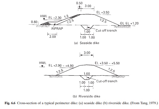
A typical design of the perimeter dike or main embankment of a coastal pond farm located in an estuarine area is shown in fig. 6.6. The dikes are aligned along the river banks onthe seaward side. If the farm is located in a man-grove area it is advisable to maintain a belt (50–100 m wide) of mangroves to protect it from waves and currents. The soft foundation soil in such swamps makes it necessary to allow for a period of natural consolidation before it becomes stable. High volume changes and surface cracks may occur in the process of drying. The height of such embankments is gen erally limited to 2.0 m, with a freeboard, after shrinkage and settlement, of 0.6–1.0 m above the design flood water level. Usually an allowance of 15–20 per cent is made for shrink-age due to settling.
A puddle trench of 0.5–1 m depth and 0.5– 1 m width is considered essential to prevent seepage under the dike. For shrimp ponds in
Southeast Asia, the following slopes are recommended (ASEAN, 1978):
2 : 1 when dike is above 4.26 m and exposed to wave action
1 : 1 when dike height is less than 4.26 m and tidal range is above 1 m
1 : 2 when the tidal range is 1 m or less and the dike height is less than 1 m.
The perimeter dike of the farm should be 0.5m above the highest tide or flood level recorded in the locality. The berm built on the inside of the dike should be slightly above the water line, in order to minimize the effects of wave action on the dikes. Holes made by burrowing animals damage the dikes in coastal ponds; the incor poration of bamboo screens or plastic film in the puddle trench helps to minimize this.
To facilitate the drainage and harvesting of fish, the pond bottom should have a minimum slope of 0.1–0.2 per cent towards the outlet. In inland fresh-water ponds, a harvest sump is constructed near the outlet in the deepest part of the pond as a long trench or in some other convenient shape, about 50 cm deeper than the surrounding area and with sloping sides to facilitate netting.
Harvesting sumps can also be constructed outside the pond, and a combined sump can be made for a number of ponds. The recommended bottom area for the harvesting (cropping) sump is around 40 m2/ha, and the depth 0.6–1 m. A width of 10–25 m would be convenient for the use of nets. The external harvesting sumps are connected to outlet sluices of the ponds and fresh water has to be introduced into the external sumps at the time of harvesting. The bottom should be at least 30 cm deeper than the deepest point of the pond and an additional differential elevation of 20 cm is necessary between the two ends of the harvesting pit.
In order to avoid rapid silting, the sump may be constructed 5–10 m away from the main dike of the pond. Low levees made of sandstones, gravel, bricks or concrete may be built around the sump to prevent silting.
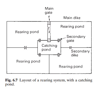
In coastal farms using tidal flow for water management, it is common to have a central canal from which tide water is taken in through a pipe and fed into a set of two or three ponds through a common catching pond (fig. 6.7). It is connected to the rearing ponds through sluice gates. The catching pond and the central canal serve the same purpose as the harvesting sumps in fresh-water ponds. For harvesting from nursery ponds, the catching ponds are particularly useful. The central canal becomes more important for harvesting from rearing or stocking ponds. The habit of many brackish-water fish to swim against the current is used to capture them. In fact, the elaborate system of ‘lavorieri’ or traps in Mediterranean lagoon farming is based on this behaviour. However, in new coastal farms, especially those meant for shrimp culture, separate feeder and drainage canals and harvesting sumps are provided. Harvesting sumps are usually located at the pond outlet.
Water supply and drainage
One of the most important factors that govern the success of an aquaculture operation is proper water management. Although tradition-
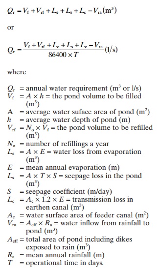
ally fish farming has been done in some areas in ‘undrainable’ ponds, the ability to intensify operations will be greatly restricted in such waters. So the adequacy of available water should be a major criterion in selecting the site. The actual quantity required for the ponds will depend on the soil and climatic conditions, but as a rule of thumb one may calculate it at the rate of 19 000–23 000 m3 for a 1 ha pond with an average depth of 1.5 m, which would include an extra 25–50 per cent more to compensate for evaporation and seepage. To have a more accurate assessment of the yearly water requirement the following formula can be used (Kovari, 1984b):
The water supply and drainage system havto be designed to convey the required quantities. Different designs have been adopted, obviously based on different criteria and requirements. In many designs, the same canals are used for feeding and drainage of water to economize on space and construction costs. In others, it is considered essential to have separate feeder and drainage canals, as well as inlets and outlets, for operational safety and efficiency. It is generally considered necessary to locate the inlets and outlets on opposite sides of a pond, but in some farm designs the inlet is located near the outlet and the harvesting sump to facilitate the supply of water to the sump when the pond is drained for harvesting.
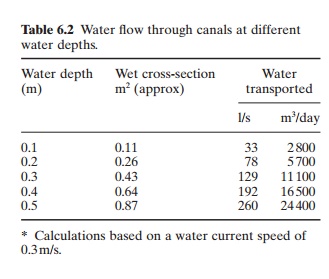
The quantity of water conveyed through a canal depends on the area of the cross-section of the water passing through (referred to some-times as the ‘wet cross-section’) and the speed of the current. This can be calculated by the equation Q = F x V, where Q is the water quantity transported in m3, F is the wet cross-section in m2 and V is the speed of water current in m/s (Woynarovich, 1975). If the bottom of the canal is 1 m wide and the slope is 1 : 1.5, the wet cross-section under different water depths will be as shown in Table 6.2.
If the bottom of the canal has a slope of 0.1–0.2 m in 1000 m, the speed of water will be about 0.3–0.5 m/s. Unless such current is maintained, rapid siltation may take place in the canals. On the other hand, faster flow may result in erosion. In areas where the soil quality is poor, lining with suitable reinforced plastic films has been successfully employed to reduce erosion and seepage from the feeder canals. It is, however, more common to construct brick or cement concretelined canals, where earthen canals are not feasible. In such cases, a higher velocity of water flow can be maintained and the width of the canal can be smaller, for example 0.4–0.5 m, with a bottom slope of 0.5– 1 m per 1000 m. When a feeder canal is built on the crest of the dikes, it is necessary to construct it with bricks or cement concrete.
The principles of designing water supply and drainage systems in coastal ponds are essentially the same as for inland fresh-water ponds.
The only major differences are caused by the tidal fluctuations, when tidal energy has to be used for filling and draining the ponds, and by the prevalence of acid sulphate soils. The tidal range data at the site will have to be used in estimating the duration and quantity of water that the farm can extract at the site at high water for feeding the ponds to the level required. Similarly, an estimate of the quantity of water that can be drained during low tides also has to be made. The size of the feeder canals and the size and number of water intakes will depend on the tidal supply. The duration of low tides and their amplitude will determine the quantity of water that can be drained from the pond. The acid sulphate soils that occur in coastal swamp areas make it necessary to drain the seepage water from the ponds, without allowing it to contaminate the water in the feeder channels. The level of water inside the pond should be maintained at a higher level than water outside the pond, to ensure that the acidic water does not stagnate there. It will also be advisable to construct a berm near the water’s edge to catch acidic run-off during rains, preventing it from washing into the ponds.
A coastal fish farm generally has a main canal and subsidiary canals for water supply and drainage. The main canal distributes from the main water gates to the subsidiary canals and from there to individual ponds. The flow is in the reverse direction for drainage. There are many types of water control structures in use in fresh-water and coastal fish farms. The inlets may be anything from a simple pipe to a concrete sluice. A turn-down pipe, open sluice or monk is used as an outlet structure. Probably the most versatile water control structure is the monk (fig. 6.8) which can be used for inlets and
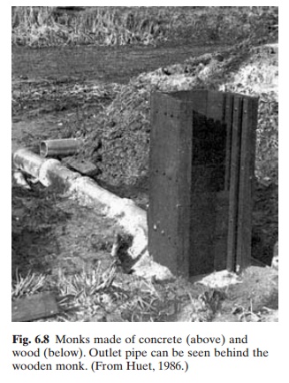
also for outlets. One major advantage is that, by adjusting the stoplog and fish screens, the operator can release the top or bottom layer of water from the pond. The monk consists of a vertical tower with three pairs of grooves for housing screens and stoplogs, and a horizontal conduit passing through the dike, both of which may be made of concrete, brick or a combination of the two. In recent years, monks made of fibreglass, plastic and even non-corrosive metal have been used. The selection of material has to be made on the basis of long-term costs, including maintenance and the economic life of the structure. The height of the tower part of the monk depends on the highest allowable water level and the size of the pipe used under the dike. The opening in front of the tower need not be more than 40 cm wide for ponds measuring up to 5 ha. Stoplogs or flash boards are inserted into two of the grooves in the monk tower. The space between the boards can be filled tightly with wet clay, barnyard manure or compost to prevent leakage of water. Another means of preventing lateral seepage is by attaching a rubber liner (the inner tube of an car tyre can be used) to the board to provide a watertight seal. The third groove is for a suitable screen to prevent debris from entering the pond and fish from escaping. It is advisable to construct wings as support for high monks. Since they are heavy structures, particularly those built with bricks or concrete, strong bases will be needed. A base 30–50 cm deep and 30 cm wide on each side will have to be constructed with boulders and cement mortar. In the case of soft soil, the base may have to be 60–90 cm deep, and 50–60 cm wider than the actual size of the structure.
Another commonly used water control structure is the open sluice (figs 6.9 and 6.10). It is especially useful where the discharges are higher than those which normal monks are capable of carrying or in catching ponds serving two adjacent ponds to facilitate the passage of fish or fry. The closing mechanism in open sluices can be stoplogs or vertical lift gates.
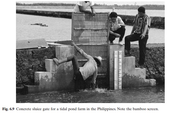
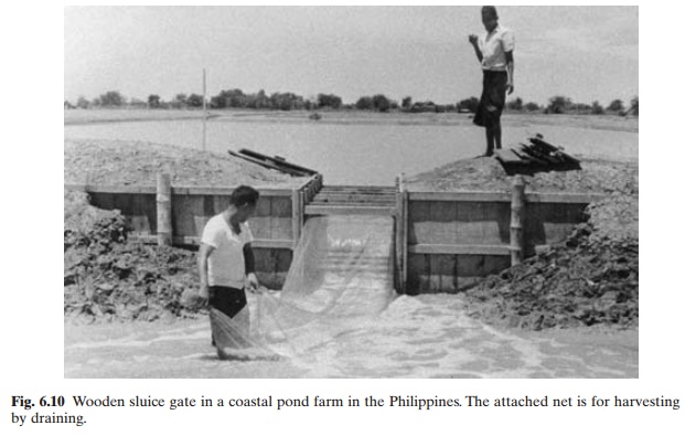
Open sluice gates are commonly used on coastal fish farms in Asia. In order to avoid poor performance due to defective workman-ship and to reduce construction costs, many farmers prefer a wooden sluice although its economical life will be shorter than that of concrete structures.
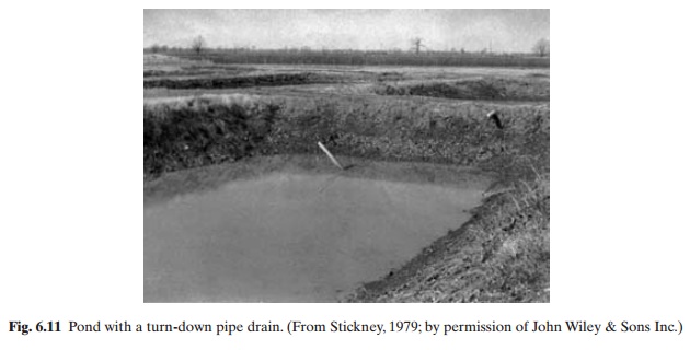
In catfish farms in the southern USA, the most popular water regulatory system is the turn-down pipe, located at the lowest point of the base of the dike. It serves as an overflow and drainpipe. The water levels can be adjusted by pivoting the pipe, in order to increase or decrease the quantity of water flowing out of the pond (fig. 6.11). Besides providing a screen over the end of the pipe inside the pond to prevent loss of fish and obstruction of water
flow by aquatic animals, it will be desirable to provide a special anti-seep collar around the drainpipe inside the dike to prevent water from seeping along the pipe and causing leaks. Some turn-down pipes are constructed with a double-sleeve device that permits water to be drained from the bottom of the pond rather than the surface (Lee, 1973). This will rectify the main disadvantage of turn-down pipes, which is their inability to drain the bottom water (low in oxygen and containing a higher percentage of metabolites). The size of pipe to be used should be selected on the basis of the size of the pond, the speed at which drainage has to be done and the rate at which the pond is to be filled. The higher the diameter of the pipe, the greater the water flow capacity. Doubling the diameter of
the pipe will result in an increase of over four times in the water flow capacity. Generally, an 11 cm pipe will be adequate for small ponds of 1–2 ha, but pipes of 16–32 cm are recommended for 6–8 ha ponds (Lee, 1973).
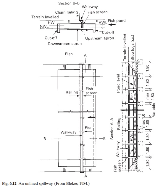
A water control structure of special importance for farms susceptible to flooding is a spill-way. This serves to bypass the floods reaching the farm, without damage to the ponds, so preventing the stock of fish from escaping. Spill-ways are also useful in farms built on level ground, when there is a large watershed area and a likelihood of surplus water caused by rainfall or by filling. A wide variety of spill-way designs are available. Unlined spillways (fig. 6.12) with fish screens between piers are relatively simple to design and construct.
When intensive aquaculture is practised, some form of aeration system becomes essential to enhance oxygen transfer and the dissolving of organic carbon in the water. Gravity aeration is often achieved through weirs and splash boards in ponds and raceways. Simple surface aerators such as open impeller or centrifugal pumps and paddle wheels are commonly used to break up or agitate the water and increase the surface area available for oxyen transfer.
Methods of construction
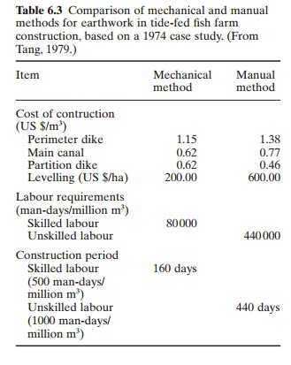
In planning construction generally, there is an option to use mechanical equipment or manual labour for much of the work involved. From an economic point of view, mechanical methods of construction have many advantages. The construction period can be greatly reduced, the need for recruitment and supervision of a large labour force can be minimized and in a majority of cases more efficient structures can be achieved. Table 6.3 shows the comparative figures for earthwork in a tidal fish farm in the Philippines.
However, under certain socio-economic situations it may be necessary to select labour-intensive methods in order to generate employment in rural areas. Also, small homestead-type fish farms can probably be constructed equally or more efficiently with manual labour. On certain swamp-land areas, particularly in peaty soils in tidal lands, the use of manual labour
may prove efficient. For example, it may be possible to adopt the technique of cutting earth into blocks and loading these on to rafts or flat-bottomed boats for transport at high tide to the embankment site. The embankment can be built at low tide, placing the blocks in the same way as bricks for building walls and compacting them mechanically or manually to make the embankment watertight. Nevertheless, overall experience so far would indicate the need to use mechanical equipment, where feasible, for construction of larger farms.
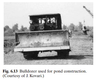
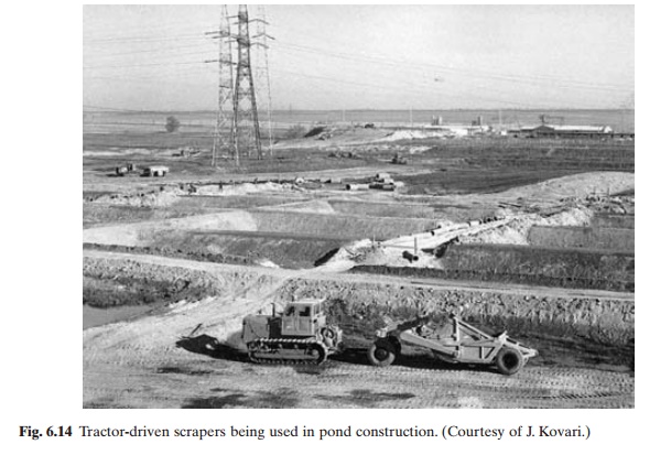
The bulldozer (fig. 6.13) is probably the most versatile earthmoving equipment for inland fresh-water farm construction as it can be used for clearing, grubbing, stripping, excavating, diking and levelling. However, the earth will have to be compacted to prevent erosion. The economical length of haul for a bulldozer is generally between 20 and 50 m. Another piece of equipment especially preferred for embank-ment construction is a scraper (fig. 6.14), which can be used for stripping, excavating and diking as well as compacting. The economical length of haul of a scraper is generally between 100 and 1000m. As a scraper does not move very easily on heavy clay, a tractor must be used to pushalong the cutting haul. Hydraulic power shovels and hoes can be useful, particularly in excavating trenches, drainage and feeder canals.
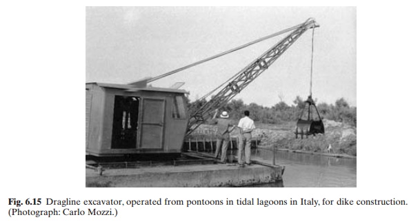
For coastal fish farm construction, a small dragline excavator (figs 6.15 and 6.16) with a bucket capacity of 0.3–0.5 m3, or a hydraulic excavator, has been found convenient for oper-ation and handling. A crawler tractor, with a lower ground contact pressure, is very suitable for trimming the soil for profile formation and also for pond-bottom levelling. The main constraint is in the haulage of earth in areas where mass movement of earth is required. Multiple handling has to be resorted to, as no other means of truck transportation is possible in swamps.
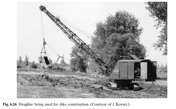
A wide variety of compactors, such as sheep-foot, steel wheel and rubber-tyred rollers and platform and vibratory compactors, are available; but in swampy soil conditions it may be difficult to use them. In such cases it has been recommended that the dikes be constructed in layers and that the dragline travels on them to effect proper compaction.
Construction materials
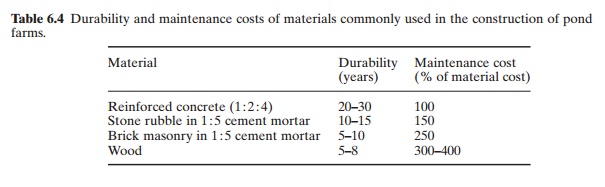
A point that needs to be emphasized in pond farm construction is the choice of construction materials. As cost and availability of materials differ so much between areas, one cannot suggest a uniform standard of materials. The guiding principle, however, should be cost-effectiveness, where durability and maintenance costs are important. Table 6.4 gives the values of durability and maintenance costs of
Schedule and sequence of construction
It is necessary to plan the construction work very carefully to avoid waste of effort, funds and efficiency of the structures. Based on project financing, availability of labour and equipment and climatic conditions, the schedule of construction and farm operation should be determined in advance. Catfish farms in the USA are often constructed during summer and autumn, allowing the soil to settle during rainy seasons in late autumn and winter. Obviously it
is preferable to complete the construction and start farming in the shortest possible time, as the investment will then start giving returns. Where a longer construction period is unavoidable, as when manual methods are employed, the possibility of constructing the farm in sections, in order to start production while construction work of the rest of the farm continues, should be considered.
In order to plan the construction work properly, a detailed contour map will have to be prepared. This can usually be done only after the site has been cleared. Clearing presents greater problems and takes more time in marshy areas, particularly mangroves. In such cases, the clearing of the area for the perimeter dike may be done first, based on the available topographic map, and the rest of the area cleared and mapped as the work progresses. It is generally easier to fell trees and remove dense brush after the perimeter dike is constructed, as the ground can then be dried to support heavy
equipment such as chain saws for cutting, pluckers for uprooting bushes and small trees, and winches for pulling the trees and brush.
The general features of the farm, including the boundary of the site, layout, number and size of ponds, main and subsidiary dikes, water supply and drainage, location of water control
structures, etc., have to be shown on the detailed map to aid construction work.The area reserved for the hatchery (if one is planned at the pond site), auxiliary buildings for storage of dry feed and chemicals, fish handling, pre-servation and storage, workshops and space for storage of nets and equipment, and the approach road and other utilities should also be shown on the map. If feed production is to be done on the farm site, adequate space for housing the equipment and feed ingredients and the storage of processed feeds has to be provided.
In order to achieve good-quality construction, the sequence of construction work of the farm has to be decided in advance and then followed. If flooding of the area during construction is likely, the drainage channels should be excavated before starting construction of the dikes. All the outlets should be constructed before commencing on the dikes. For the actual construction of the dikes it is necessary to estimate the quantity of earth required (taking into account also the packing coefficient of the soil, usually 20–50 per cent) and decide whether the pond area should be excavated for obtaining the earth and for levelling the pond bottom. The quantity of earth required per hectare for the construction of dikes for a 4 ha pond is estimated to be 2500–4000 m3 (Pruginin and Ben-Ari, 1959). As far as possible, all organic matter, including roots, should be removed from the soil used for dike construction, as rotting organic matter will weaken the dike. Similarly, the humus should be removed from the base of the dike to bind the dike to the base properly and avoid seepage. The need to preserve the top soil in ponds built on catclay soils and allow a layer of silt to settle on it to reduce hazards of acidity in pond water has already been discussed. To attain the desired height of the dike, it may be necessary to compensate for subsidence by recapping it two or three times. It may also be necessary to make a large berm between the toe of the dike and the drainage canal, to offset the weight of the dike.
Related Topics