Chapter: Civil : Design of Reinforced Concrete Elements : Limit State Design Of Columns
Design Problem, Important Question And Answer: Civil - Limit State Design Of Columns
Design Problems
1.Determine the load carrying capacity of a column
of size 300 x 400 mm reinforced with six rods of 20 mm diameter i.e, 6-#20. The
grade of concrete and steel are M20 and Fe 415 respectively. Assume that the
column is short.
fck = 20 MPa, fy=
415 MPa
Area of
steel ASC = 6 x ? x 202/4
= 6 x 314 = 1884 mm2 Percentage of steel = 100Asc/bD =
100x1884/300x400 = 1.57 % Area of concrete Ac = Ag - Asc
= 300 x 400 - 1884 = 118116 mm2 Ultimate load carried by the column
Pu = 0.4 fck Ac
+ 0.67 fy Asc
0.4x20x118116 +
0.67x415x1884
944928 + 523846 = 1468774
N = 1468. 8 kN
Therefore the safe load on
the column = 1468.8 /1.5 = 979.2 kN
2.Determine the steel required to
carry a load of 980kN on a rectangular column of size 300 x 400 mm. The grade
of concrete and steel are M20 and Fe 415 respectively. Assume that the column
is short.
fck
= 20 MPa, fy= 415 MPa, P = 980 kN Area of steel ASC = ?
Area of concrete Ac =
Ag - Asc = (300 x 400 -
ASC)
Ultimate load carried by the
column
Pu = 0.4 fck Ac
+ 0.67 fy Asc
980 x 1.5 x 1000 = 0.4x20x (300 x
400 - ASC) + 0.67x415 ASC
= 960000 - 8 ASC
+ 278.06 ASC
ASC =1888.5 mm2,
Percentage
of steel = 100Asc/bD = 100x1888.5 /300x400 = 1.57 % which is more than 0.8% and
less than 6% and therefore ok.
Use 20 mm dia. bas, No. of bars =
1888.5/314 = 6.01 say 6
3.Design a square or circular column to carry a
working load of 980kN. The grade of concrete and steel are M20 and Fe 415
respectively. Assume that the column is short.
Let us assume 1.0% steel (1 to
2%)
Say ASC
= 1.0% Ag =1/100 Ag = 0.01Ag fck =
20 MPa, fy= 415 MPa, P = 980 kN
Area of concrete Ac =
Ag - Asc = Ag
-0.01Ag = 0.99 Ag
Ultimate
load carried by the column Pu = 0.4 fck Ac +
0.67 fy Asc
980 x 1.5 x 1000 = 0.4x20x 0.99 Ag + 0.67x415 x
0.01Ag = 7.92 Ag + 2.78 Ag =10.7Ag
Ag =
137383 mm2
Let us design a square column:
B = D = ? Ag =370.6 mm say 375 x 375 mm
This is
ok. However this size cannot take the minimum eccentricity of 20 mm as emin/D
= 20/375 =0.053 > 0.05. To restrict the eccentricity to 20 mm, the required
size is 400x 400 mm.
Area of
steel required is Ag = 1373.8 mm2. Provide 4 bar of 22 mm
diameter. Steel provided is 380 x 4 = 1520 mm2
Actual
percentage of steel = 100Asc/bD = 100x1520 /400x400 = 0.95 % which
is more than 0.8% and less than 6% and therefore ok.
Design of Transverse
steel:
Diameter
of tie = � diameter of main steel = 22/4 =5.5mm or 6 mm, whichever is greater.
Provide 6 mm.
Spacing: < 300 mm, < 16 x22
= 352mm, < LLD = 400mm. Say 300mm c/c
Design of circular column:
Here Ag = 137383 mm2
? x D2/4 = Ag, D= 418.2 mm say 420 mm.
This satisfy the minimum eccentricity of 20m Also
provide 7 bars of 16 mm, 7 x 201 = 1407 mm2
Design of Transverse
steel:
Dia of tie = � dia of main steel
= 16/4 = 4 mm or 6 mm, whichever is greater. Provide 6 mm.
Spacing: < 300 mm, < 16 x16
= 256 mm, < LLD = 420mm. Say 250 mm c/c
4.Design a rectangular column to carry an ultimate
load of 2500kN. The unsupported length of the column is 3m. The ends of the
column are effectively held in position and also restrained against rotation.
The grade of concrete and steel are M20 and Fe 415 respectively.
Given:
fck
= 20 MPa, fy= 415 MPa, Pu
= 2500kN
Let us assume
1.0% steel (1 to 2%)
Say ASC = 1.0% Ag =1/100 Ag
= 0.01Ag
Area of
concrete Ac = Ag - Asc = Ag -0.01Ag = 0.99 Ag
Ultimate load carried by the column Pu = 0.4 fck
Ac + 0.67 fy Asc
2500 x 1000 = 0.4x20x 0.99 Ag + 0.67x415 x 0.01Ag
= 7.92 Ag + 2.78 Ag =10.7Ag
Ag =
233645 mm2
If it is
a square column:
B = D = ? Ag =483 mm. However
provide rectangular column of size 425 x 550mm. The area provided=333750 mm2
Area of
steel = 2336 mm2, Also provide 8 bars of 20 mm, 6 x 314 = 2512 mm2
Check for
shortness: Ends are fixed. lex = ley
= 0.65 l = 0.65 x 3000 = 1950 mm
lex
/D= 1950/550 < 12, and ley
/b = 1950/425 < 12, Column is short
Check for
minimum eccentricity:
In the
direction of longer direction
emin,
x = lux/500 + D/30 = 3000/500 + 550/30 = 24.22mm or 20mm
whichever is greater.
emin,
x = 24.22 mm < 0.05D = 0.05 x
550 =27.5 mm. O.K
In the
direction of shorter direction
emin,
y= luy/500 + b/30 = 3000/500 + 425/30 = 20.17 mm or 20mm
whichever is greater.
emin,
x = 20.17 mm < 0.05b = 0.05 x
425 =21.25 mm. O.K
Design of
Transverse steel:
Dia of tie = � dia of main steel = 20/4 = 5 mm or 6 mm,
whichever is greater. Provide 6 mm or 8 mm.
Spacing:
< 300 mm, < 16 x20 = 320 mm, < LLD = 425mm. Say 300 mm c/c
5.Design a circular column with ties to carry an
ultimate load of 2500kN. The unsupported length of the column is 3m. The ends
of the column are effectively held in position but not against rotation. The
grade of concrete and steel are M20 and Fe 415 respectively.
Given:
fck = 20 MPa, fy=
415 MPa, Pu = 2500kN
Let us assume 1.0% steel (1 to
2%)
Say ASC = 1.0% Ag =1/100 Ag
= 0.01Ag
Area of concrete Ac =
Ag - Asc = Ag
-0.01Ag = 0.99 Ag
Ultimate
load carried by the column Pu = 0.4 fck Ac +
0.67 fy Asc
2500 x 1000 = 0.4x20x 0.99 Ag + 0.67x415 x 0.01Ag
= 7.92 Ag + 2.78 Ag =10.7Ag
Ag =
233645 mm2
? x D2/4 = Ag, D = 545.4 mm say 550 mm.
Area of steel = 2336 mm2,
Also provide 8 bars of 20 mm, 6 x 314 = 2512 mm2
Check for shortness: Ends
are hinged lex = ley = l = 3000 mm
lex /D= 3000/550 <
12, and ley /b = 3000/425
< 12, Column is short
Check for minimum
eccentricity:
Here, emin,
x = emin, y = lux/500 + D/30 = 3000/500 + 550/30 =
24.22mm or 20mm whichever is greater.
emin =
24.22 mm < 0.05D = 0.05 x 550 =27.5 mm. O.K
Design of Transverse
steel:
Diameter
of tie = � dia of main steel = 20/4 = 5 mm or 6 mm, whichever is greater.
Provide 6 mm or 8 mm.
Spacing: < 300 mm, < 16 x20
= 320 mm, < LLD = 550mm. Say 300 mm c/c
Similarly square column can be
designed.
If the
size of the column provided is less than that provided above, then the minimum
eccentricity criteria are not satisfied. Then emin is more and the
column is to be designed as uni axial bending case or bi axial bending case as
the case may be. This situation arises when more steel is provided ( say 2% in
this case).
Try to solve these problems by
using SP 16 charts, though not mentioned in the syllabus.
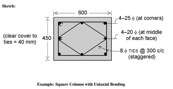
6.Design the reinforcement in a column of size 450
mm � 600 mm, subject to an axial load of 2000 kN under service dead and live
loads. The column has an unsupported length of 3.0m and its ends are held in
position but not in direction. Use M 20 concrete and Fe 415 steel.
Solution:
Given: lu= 3000 mm, b = 450 mm, D = 600
mm, P =2000kN, M20, Fe415
Check for shortness: Ends
are fixed. lex = ley = l
= 3000 mm
lex /D= 3000/600 <
12, and ley /b = 3000/450<
12, Column is short
Check for minimum
eccentricity:
In the direction of longer
direction
emin,
x = lux/500 + D/30 = 3000/500 + 600/30 = 26 mm or 20mm
whichever is greater. emin, x = 26 mm < 0.05D = 0.05 x 600 =30
mm. O.K
In the direction of shorter
direction
emin,
y= luy/500 + b/30 = 3000/500 + 450/30 = 21 mm or 20mm
whichever is greater. emin, x = 21 mm < 0.05b = 0.05 x 450 =22.5
mm. O.K
Minimum
eccentricities are within the limits and hence code formula for axially loaded
short columns can be used.
Factored Load
|
P |
= service load � partial
load factor |
|
U |
|
|
|
= 2000 � 1.5 = 3000 kN |
|
Design
of Longitudinal Reinforcement |
|
|
Pu |
= 0.4 fck Ac
+ 0.67 fy Asc
or |
|
Pu |
= 0.4
fck Ac + (0.67 fy - 0.4fck) Asc |
3
3000 � 10 = 0.4 � 20 � (450 � 600) + (0.67 � 415-0.4 �
20)Asc
3
=
2160�10 + 270.05Asc
? Asc = (3000-2160) �
10 /270.05 = 3111 mm
In view of the column dimensions
(450 mm, 600 mm), it is necessary to place intermediate
bars, in addition to the 4
corner bars:
2
Provide 4-25? at corners ie, 4 � 491 = 1964 mm
2
and 4-20? additional ie, 4 � 314 = 1256 mm
2 2
? Asc
= 3220 mm > 3111 mm
? p =
(100�3220) / (450�600) = 1.192 > 0.8 (minimum steel), OK.
Design of transverse steel
Diameter
of tie = � diameter of main steel = 25/4 =6.25 mm or 6 mm, whichever is
greater. Provide 6 mm.
Spacing:
< 300 mm, < 16 x 20 = 320 mm, < LLD = 450mm. Say 300 mm c/c Thus
provide ties 8mm @ 300 mm c/c
Sketch:
7.Determine the reinforcement to be provided in a
square column subjected to uniaxial bending with the following data:
Size of column 450 x 450 mm
Concrete mix M 25
Characteristic strength of steel
415 N/mm2
Factored load 2500 kN
Factored moment 200 kN.m
Arrangement of reinforcement:
(a)On two
sides
(b)
On four sides
Assume
moment due to minimum eccentricity to be less than the actual moment Assuming
25 mm bars with 40 mm cover, d = 40 + 12.5 = 52.5 mm d1/D
= 52.5/450- 0.12
Charts for d1/D = 0.15
will be used
Pu/fckbD =
(2500 x 1000)/ (25 x 450 x 450) = 0.494
Mu/fckbD2
=200 x 106 /(25 x 450 x 4502) = 0.088
a) Reinforcement on two sides,
Referring
to Chart 33, p/fck = 0.09
Percentage
of reinforcement, p = 0.09 x 25 = 2.25 %
As = p bD/100
= 2.25 x 450 x 450/100 = 4556 mm2
b)
Reinforcement on four sides from Chart 45,
p/fck = 0.10
p = 0.10 x 25 = 2.5 %
As = 2.5 x 450 x
450/100 = 5063 mm2
8.Example: Circular Column with Uniaxial Bending
Determine
the reinforcement to be provided in a circular column with the following data:
Diameter
of column 500 mm Grade of concrete M20 Characteristic strength 250 N/mm2
Factored load 1600 kN
Factored moment 125 kN.m
Lateral reinforcement :
(a)Hoop
reinforcement
(b)
Helical reinforcement
(Assume
moment due to minimum eccentricity to be less than the actual moment). Assuming
25 mm bars with 40 mm cover,
d1
= 40 + 12.5 = 52.5 mm d1/D - 52.5/50 = 0.105
Charts for d'/D = 0.10
will be used.
(a) Column with hoop
reinforcement
Pu/fck D D
= (1600 x 1000)/ (20 x 500 x 500) = 0.32
Mu/fck
D x D2 =125 x 106 /(20 x 500 x 5002) = 0.05
Referring
to Chart 52, for fy = 250 N/mm2 p/fck
= 0.87
Percentage
of reinforcement, p = 0.87 x 20 = 1.74 %
As = 1.74 x (? x 5002/4)/100 = 3416 mm2
(b) Column with Helical
Reinforcement
According
to 38.4 of the Code, the strength of a compression member with helical
reinforcement is 1.05 times the strength of a similar member with lateral ties.
Therefore, the, given load and moment should be divided by 1.05 before
referring to the chart.
Pu/fck D D
= (1600/1.05 x 1000)/ (20 x 500 x 500) = 0.31
Mu/fck D x
D2 =125/1.05 x 106 /(20 x 500 x 5002) = 0.048
Hence, From Chart 52, for fy
= 250 N/mm2,
p/fck = 0.078
p = 0.078 x 20 = 1.56 %
As = 1.56 x( ? x 500 x 500/4 )/100 = 3063 cm2
According
to 38.4.1 of the Code the ratio of the volume of helical reinforcement to the
volume of the core shall not be less than
0.36 (Ag/Ac
- 1) x fck /fy
where Ag
is the gross area of the section and Ac is the area of the
core measured to the outside diameter of the helix. Assuming 8 mm dia bars for
the helix,
Core diameter = 500 - 2 (40 - 8)
= 436 mm
Ag/AC = 500/436
= 1.315
0.36 (Ag/Ac
- 1) x fck /fy = 0.36(0.315) 20/250 =0.0091
Volume of helical reinforcement /
Volume of core
= Ash
? x 428 /( ?/4 x 4362) sh
0.9 Ash
/ sh
where, Ash
is the area of the bar forming the helix and sh is the pitch of the
helix. In order to satisfy the coda1 requirement,
0.09 Ash / sh ? 0.0091
For 8 mm dia bar,
sh ? 0.09 x
50 / 0.0091 = 49.7 mm. Thus provide 48 mm pitch
Example: Rectangular column with Biaxial Bending
9.Determine the reinforcement to be provided in a
short column subjected to biaxial bending, with the following data:
size of
column = 400 x 600 mm Concrete mix = M15
Characteristic
strength of reinforcement = 415 N/mm2 Factored load, Pu =
1600 kN
Factored
moment acting parallel to the larger dimension, Mux =120 kNm Factored
moment acting parallel to the shorter dimension, Muy = 90 kNm
Moments due to minimum eccentricity are less than the values given above.
Reinforcement is distributed
equally on four sides.
As a
first trial assume the reinforcement percentage, p = 1.2% p/fck
= 1.2/15 = 0.08
Uniaxial moment capacity of the
section about xx-axis :
d1/D = 52.5 /600 =
0.088
Chart for d'/D = 0.1 will be
used.
Pu/fck b D
= (1600 x 1000)/ (15 x 400 x 600) = 0.444
Referring to chart 44
Mu/fck b x
D2 = 0.09
Mux1 = 0.09 x 15 x 400
x 6002) = 194.4 kN.m
Uni-axial moment capacity of the
section about yy axis :
d1/D = 52.5 /400 =
0.131
Chart for
d1/D =0.15 will be used. Referring to Chart 45,
Mu/fck b x
D2 = 0.083
Mux1 = 0.083 x 15 x
600 x 4002) = 119.52 kN.m
Calculation of Puz :
Referring
to Chart 63 corresponding to p = 1.2, fy = 415 and fck =
15,
Puz/Ag =
10.3
Puz = 10.3 x 400 x 600
= 2472 kN
Mux/Mux1 =
120/194.4 =0.62
Muy/Muy1=90/119.52
= 0.75
Pu /Puz =1600/2472 = 0.65 Referring to Churn 64, the permissible
value of Mux/Mux1 corresponding to Muy/Muy1
and Pu /Puz is equal to 0.58
The
actual value of 0.62 is only slightly higher than the value read from the Chart.
This can
be made up by slight increase in reinforcement.
Using
Boris load contour equation as per IS:456-2000
Pu
/Puz = 0.65 thus, ?n = 1 +
[(2-1) / (0.8 - 0.2)] (0.65-0.2) = 1.75
[0.62 ]1.75 + [0.75]1.75 = 1.04 slightly
greater than 1 and slightly unsafe. This can be made up by slight increase in
reinforcement say 1.3%
Thus
provide As = 1.3x400x600/100 = 3120 mm2
Provide 1.3 % of steel p/fck = 1.3/15 = 0.086
d1/D
= 52.5 /600 = 0.088 = 0.1
From
chart 44
Mu/fck
b x D2 = 0.095
Mux1
= 0.095 x 15 x 400 x 6002) = 205.2
kN.m
Referring
to Chart 45,
Mu/fck
b x D2 = 0.085
Mux1
= 0.085 x 15 x 600 x 4002) = 122.4 kN.m
Chart 63
: Puz/Ag = 10.4
Puz
= 10.4 x 400 x 600 = 2496 kN
Mux/Mux1
= 120/205.2 =0.585
Muy/Muy1=90/122.4 = 0.735
Pu
/Puz =1600/2496 = 0.641
Referring to Chart 64, the permissible value of Mux/Mux1
corresponding to Muy/Muy1 and Pu /Puz
is equal to 0.60
Hence the
section is O.K.
Using
Boris load contour equation as per IS:456-2000
Pu
/Puz = 0.641 thus, ?n = 1 +
[(2-1) / (0.8 - 0.2)] (0.641-0.2) =
1.735
[120/205.2]1.735
+ [90/122.4]1.735 = 0.981 ? 1 Thus
OK
As = 3120 mm2. Provide 10 bars of 20 mm dia. Steel
provided is 314 x 10 = 3140 mm2
Design of transverse steel: Provide 8 mm dia stirrups at 300
mm c/c as shown satisfying the requirements of IS: 456-2000
10.Verify the adequacy of the short column section
500 mm x 300 mm under the following load conditions:
Pu = 1400 kN, Mux
= 125 kNm, Muy = 75 kNm. The design interaction curves of SP 16
should be
used. Assume that the column is a 'short column' and the eccentricity due to
moments is greater than the minimum eccentricity.
Solution:
2
Given: D = 500 mm, b = 300 mm, A = 2946 mm M =
125 kNm, M = 75 kNm, f = 25
x s ux uy ck
MPa, f = 415 MPa
y
Applied eccentricities
3
ex = Mux/Pu
= 125 � 10 /1400 = 89.3 mm ? ex/Dx =
0.179
3
ey = Muy/Pu
= 75 � 10 /1400 = 53.6 mm ? ey/Dy =
0.179
These eccentricities for the short column are clearly not less
than the minimum eccentricities specified by the Code.
Uniaxial moment capacities: Mux1,
Muy1
As determined in the earlier
example, corresponding to P = 1400 kN,
u
M = 187 kNm
ux1
Muy1 = 110 kNm Values of Puz and ?n
Puz = 0.45fck
Ag + (0.75fy - 0.45fck)Asc
= (0.45 �
25 � 300 � 500) + (0.75 � 415 - 0.45 � 25)�2946
= (1687500
+ 883800)N = 2571 kN
? Pu/Puz
= 1400/2571 = 0.545 (which lies between 0.2 and 0.8)
? ?n = 1.575
Check safety under biaxial
bending
[125/187]1.575 +
[75/110]1
= 0.530 +
0.547
1.077 > 1.0 Hence, almost ok.
Related Topics