Chapter: VLSI Design : Specification Using Verilog HDL
Data Flow and RTL
DATA FLOW AND RTL
In
verilog coding gate-level modeling works well due to the number of gates are
less; if large number of gates are used in a circuit then this type of modeling
will be complicated. Dataflow modeling is a powerful approach to implement
large circuit. This modeling becomes a popular approach as logic synthesis
tools have become difficult.
1. Continuous
assignments:
Continuous
assignments are one type of concurrent statements . While gate
instantiations
allow the description of a circuit’s structure, continuous assignments allow
the description of a circuit’s function. General form of the continuous
statement is assign net_assignment {, net_assignment};thenet_assignment can be
any expression involving the operators.
Example:
assign
carry = (a & b) | (a & c) | (b & c);
assign
sum = a ^ b ^ c;
multiple
assignments are specified in one assignment, using commas to separate the
assignment.
Example:
assign
carry = (a & b) | (a & c) | (b & c), sum = a ^ b ^ c;
Example for multibit assignment is wire
[1:3] x, y, z;
assign z
= x & y;
This
results in z1 = x1y1, z2 = x2y2, z3 = x3y3. Delays in dataflow modeling:
Delay
values control the time between the change in a right hand side operand and
when thenew value is assigned to the left hand side. Delays in continuous
assignment statements can be specified in three ways:
a)
Regular assignment delay
b) Implicit
continuous assignment delay
c)
Net declaration delay
2. Regular assignment
delay:
In this
way, the delay value can be specified after the keyword assign.
Example:
assign
#10 c = a & b;
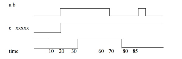
1.
When the input a and b go to high at time 20, c
goes to high at 10 time units later.
2.
When a goes low at 60, c goes to low at 70.
3.
When a changes to high at 80, but it goes down to
low before 10 time units have over and done.
4.
So, at the time of recomputation, 10 units after
80, a is 0. Thus, c gets the value 0.
3. Implicit continuous
assignment delay:
Implicit
continuous assignment method is used to specify both a delay and an assignment
on the net.
Example:
wire c;
assign
#10 c = a & b;
In
implicit continuous assignment delay we can write the above as:
wire #10
c = a & b;
4. Net declaration
delay:
Net
declaration delays can be used in gate level modeling. Delay can be specified
on a net when it is declared without putting a continuous assignment on the
net. If a delay is specified on a net c, then any value change applied to the
net c is delayed accordingly.
Example:
wire c;
assign
#10 c = a & b;
We can
write the above by using net declaration delay as: wire #10 c;
assign c
= a & b;
Related Topics