Chapter: Basic Electrical : Electrical Machines
DC Generator
DC Generator
DC Generator:
To change the Simple Generator into a
direct-current generator, two things must be done:(1) The current must be
conducted from the rotating loop of wire(2) The current must be made to move in
only one direction. A device called a commutator performs both tasks.
DC generator construction:
What is
Generator?
An electrical generator is a
device that converts mechanical energy to electrical energy, generally using electromagnetic
induction. The source of mechanical energy may be a reciprocating or turbine steam
engine, water falling through a turbine or waterwheel, an internal combustion
engine, a wind turbine, a hand crank, or any other source of mechanical energy.
The
Dynamo was the first electrical generator capable of delivering power for
industry. The dynamo uses electromagnetic principles to convert mechanical
rotation into an alternating electric current. A dynamo machine consists of a
stationary structure which generates a strong magnetic field, and a set of
rotating windings which turn within that field. On small machines the magnetic
field may be provided by a permanent magnet; larger machines have the magnetic
field created by electromagnets.
The
energy conversion in generator is based on the principle of the production of
dynamically induced e.m.f. whenever a conductor cuts magneticic flux,
dynamically induced e.m.f is produced in it according to Faraday's Laws of
Electromagnetic induction. This e.m.f causes a current to flow if the conductor
circuit is closed. Hence, two basic essential parts of an electrical generator
are (i) a magnetic field and (ii) a conductor or conductors which can so move
as to cut the flux.
Here is the construction diagram
of dc generator:
Generator
Construction:
Simple
loop generator is having a single-turn rectangular copper coil rotating about
its own axis in a magnetic field provided by either permanent magnet or electro
magnets. In case of without commutator the two ends of the coil are joined to
slip rings which are insulated from each other and from the central shaft.Two
collecting brushes (of carbon or copper) press against the slip rings.Their
function is to collect the current induced in the coil. In this case the
current waveform we obtain is alternating current ( you can see in fig). In
case of with commutator the slip rings are replaced by split rings.In this case
the current is unidirectional.
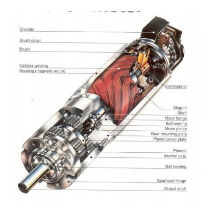
Components of a generator:
Yoke: Yoke is a outer frame. It serves two purposes.
(i) It
provides mechanical support for the poles and acts as a protecting cover for
the whole machine and
(ii) It
carries the magnetic flux produced by the poles.
In small
generators where cheapness rather than weight is the main consideration, yokes
are made of cast iron. But for large machines usually cast steel or rolled
steel is employed. The modern process of forming the yoke consists of rolling a
steel slab round a cylindrical mandrel and then welding it at the bottom. The
feet and the terminal box etc., are welded to the frame afterwards. Such yokes
possess sufficient mechanical strength and have high permeability.
Rotor: In its simplest form, the rotor consists of a single loop of wire
made to rotate within a magnetic field. In practice, the rotor
usually consists of several coils of wire wound on an armature.
Armature: The armature is a cylinder of laminated iron mounted on an axle.
The axle is carried in bearings mounted in the
external structure of the generator. Torque is applied to the axle to make the
rotor spin.
Coil: Each coil usually consists of many turns of copper wire wound on
the armature. The two ends of each coil are connected
either to two slip rings (AC) or two opposite bars of a split-ring commutator
(DC).
Stator: The stator is the fixed part of the
generator that supplies the magnetic field in which the coils rotate. It may consist of two
permanent magnets with opposite poles facing and shaped to fit around the
rotor. Alternatively, the magnetic field may be provided by two electromagnets.
Field
electromagnets: Each electromagnet consists of a coil
of many turns of copper wire wound on a soft iron core. The
electromagnets are wound, mounted and shaped in such a way that opposite poles
face each other and wrap around the rotor.
Brushes: The brushes are carbon blocks that maintain contact with the ends
of the coils via the slip rings (AC) or the split-ring
commutator (DC), and conduct electric current from the coils to the external
circuit.
Principle of operation:
DC generator converts mechanical energy into
electrical energy. when a conductor move in a magnetic field in such a way
conductors cuts across a magnetic flux of lines and emf produces in a generator
and it is defined by faradays law of electromagneticinduction :emf causes
current to flow if the conductor circuit is closed.
Applications of DC generator:
1. Shunt
generators are extensively used for general light and power supply, and for
charging of batteries, since, in conjunction with a field regulator, a constant
terminal voltage can be maintained at all loads.
2. Series
generators are mainly used as animation boosters in dc transmission system, in
order to compensate for the drop of voltage due to the resistance of
transmission conductors.
3. Over-compounded
generators find use in dc transmission, since it is possible to keep on a
constant voltage at the load end, by generating a larger voltage so as to
overcome the line drop.
Related Topics