Chapter: Solid State Drives : Converter / Chopper Fed DC Motor Drive
Continuous Armature Current
Continuous Armature Current
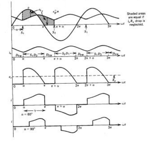
Let us assume that the armature current is continuous over the whole range of operation. Typical voltage and current waveforms are shown in Figs.2.2 and 2.3 for semi-converter and full-converter systems, respectively. The thyristors are symmetrically triggered. In the semi-converter system shown in Fig.2.2, thyristor Sl is triggered at an angle a and S2 at an angle a+7T with respect to the supply voltage v. In the full-converter system shown in Fig.2.3, thyristors S,and S3 are simultaneously triggered at a, thyristors S2 and S4 are triggered at 7T +a.
In Fig. 2.2, the motor is connected to the input supply for the period a<wt<7T through Sl and D2, and the motor terminal voltage ea is the same as the supply input voltage v. Beyond 7T, ea tends to reverse as the input voltage changes polarity. This will forward-bias the free-wheeling diode and DFW will start conducting. The motor current ia, which was flowing from the supply through Sl' is transferred to DFW (i.e., Sl commutates). The motor terminals are shorted through the free-wheeling diode during 7T <wt <(7T +a),making eo zero. Energy from the supply is therefore delivered to the armature
Circuit when the thyristor conducts (a to7T). This energy is partially stored in the inductance, partially stored in the kinetic energy (K.E.) of the moving system, and partially used to supply the mechanical load. During the free-wheeling period, 7T to7T +a, energy is recovered from the inductance and is converted to mechanical form to supplement the K.E.in supplying the mechanical load. The free-wheeling armature current continues to produce electromagnetic torque in the motor. No energy is feedback to the supply during this period.
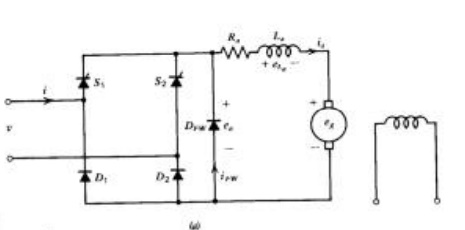
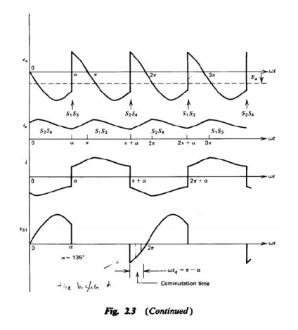
In Fig.2.3, the motor is always connected to the input supply through the thyristors. Thyristors Sl and S3conduct during the interval a<wt <(7T +a) and connect the motor to the supply. At 7T +a, thyristors S2 and S4 are triggered. Immediately the supply voltage appears across the thyristors Sl and S3asa reverse-bias voltage and turns them off. This is called natural or line commutation. The motor current ia, which was flowing from the supply through Sl and S3' is transferred to S2 and S4. During at o7T,energy flows from the input supply to the motor (both v and ia repositive, and eo and io are positive, signifying positive power flow). However, during 7T to 7T +a, some of the motor system energy is feedback to the input supply(v and I have opposite polarities and likewise ea and io' signifying reverse power flow).
In Fig.2.3c voltage and current waveforms are shown for a firing angle greater than 90°.The average motor terminal voltage Eo is negative. If the motor back emf Eg is reversed, it will behave as a de-generator and will feed power back to the ac supply. This is known as the inversion operation of the converter, and this mode of operation is used in the regenerative braking of the motor.
Torque Speed Characteristics
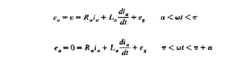
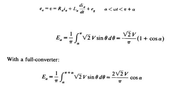
For a semi-converter with free-wheeling action the armature circuit equations are:
Single-Phase Separately Excited DC Motor Drives
The armature circuit equation for a full-converter is:
Related Topics