Chapter: Special Electrical Machines : Permanent Magnet Brushless D.C. Motors
Constructional Features of BLPM Motors
CONSTRUCTIONAL FEATURES OF BLPM
MOTORS
1. Construction
The
stator of the BLPM dc motor is made up of silicon steel stampings with slots in
its interior surface. These slots accommodate either a closed or opened
distributed armature winding usually it is closed. This winding is to be wound
for a specified number of poles. This winding is suitably connected to a dc supply
through a power electronic switching circuitry (named as electronic
commutator).
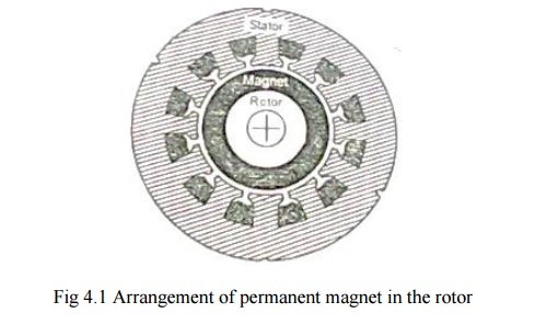
Rotor is
made of forged steel. Rotor accommodates permanent magnet. Number of poles of
the rotor is the same as that of the stator. The rotor shaft carries a rotor
position sensor. This position sensor provides information about the position
of the shaft at any instant to the controller which sends suitable signals to
the electronic commutator.
2. Merits and Demerits
Merits
v There is
no field winding. Therefore there is no field cu loss.
v The
length of the motor is less as there is no mechanical commutator.
v Size of
the motor becomes less.
v It is
possible to nave very high speeds.
v It is
self-starting motor. Speed can be controlled.
v Motor can
be operated in hazardous atmospheric condition.
v Efficiency
is better.
Demerits
v Field
cannot be controlled.
v Power
rating is restricted because of the maximum available size of permanent
magnets.
v A rotor
position sensor is required.
v A power
electronic switch circuitry is required.
3. Comparison of brushless dc
motor relative to induction motor drives
v In the
same frame, for same cooling, the brushless PM motor will have better
efficiency and p.f and therefore greater output. The difference may be in the
order of 20 ŌĆō 50% which is higher.
v Power
electronic converter required is similar in topology to the PWM inverters used
in induction motor drives.
v In case
of induction motor, operation in the weakening mode is easily achieved
providing a constant power capability at high speed which is difficult in BLPM
dc motor.
v PM
excitation is viable only in smaller motors usually well below 20 kw also
subject to speed constraints, In large motors PM excitation does not make sense
due to weight and cost.
4.
Commutator and brushes arrangement
Because of the hetropolar magnetic field in the air
gap of dc machine the emf induced in the armature conductors is alternating in
nature. This emf is available across brushes as unidirectional emf because of
commutator and brushes arrangement.
The dc current passing through the brushes is so
distributed in the armature winding that unidirectional torque is developed in
armature conductor.
A dc current passing through the brushes because of
commutator and brushes action, always sets up a mmf whose axis is in quadrature
with the main field axis, irrespective of the speed of the armature.
5. Construction of Mechanical
Commutator
Commutator Segment
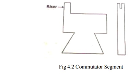
Commutator
is made up of specially shaped commutator segments made up of copper. These
segments are separated by thin mica sheets (ie) Insulation of similar shape.
The commutator segments are tapered such that when assembled they form a
cylinder.
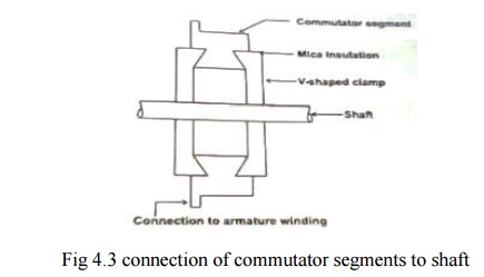
These
segments are mechanically fixed to the shaft using V ŌĆō shaped circular steel
clamps, but are isolated electrically from the shaft using suitable insulation
between the clamps and the segment.
6. Mechanical Commutator and
Brushes Arrangement
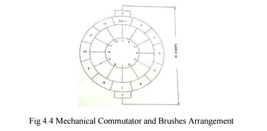
It
represents a case with 2poles and 12 commutator segments.
To start
with the brush X contacts with CSI and brush Y with 7.A dc supply is connected
across the brushes X and Y. The dc current I passes through brush X,CSI,tapping
1,tapping
7and brush Y. There are two armature parallel paths between tappingŌĆśs 1 and
7.the current passing through the armature winding aets up a magneto motive
force whose axis is along the axes of tapping 7 and 1 of the brush axes Y and
X.
Allow the
armature to rotate by an angle in a counter clockwise direction. Then the brush
X contacts CS2 and the tappingŌĆśs a and the brush Y. Contact CS8 and tapping
8.The dc current passes through the tappingŌĆśs 2 and 8 there are two parallel
paths.
(i)
2 ŌĆō 3 ŌĆō 4 ŌĆō 5 ŌĆō 6 ŌĆō 7 ŌĆō 8
(ii)
2 ŌĆō 1 ŌĆō 12 ŌĆō 11 ŌĆō 10 ŌĆō 9 ŌĆō 8
Now the
mmf set up by the armature winding is form tapping 8 to 2 along the brush axis
YX Thus the armature mmf direction is always along the brush axis YX, even
though the current distribution in the armature winding gets altered.
In a
normal dc machine brushes are kept in the interpolar axis. Therfore, the axis
of the armature mmf makes an angle 90˚elec with the main field axis.
The
function of commutator and brushes arrangement in a conventional dc machine is
to set up an armature mmf always in quadrature with the main field mmf
respectively of the speed of rotation of the rotor.
7. Electronic commutator
The armature winding which is in the stator has 12 tappingŌĆśs. each tapping is connected to the positive of the dc supply node and through 12 switches designated as S1 ,S2,ŌĆ”.S12 and negative of the supply at node Y through switches SŌĆś1,SŌĆś2,ŌĆ”ŌĆ”.SŌĆś12.
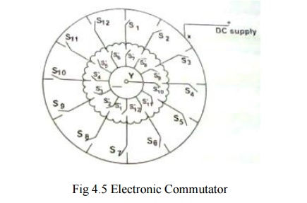
When S1
and SŌĆś1 are closed the others are in open position, the dc supply is given to
the trappings 1 and 7.there are two armature parallel path.
(i)
1 ŌĆō 2 ŌĆō 3 ŌĆō 4 ŌĆō 5 ŌĆō 6 ŌĆō 7
(ii)
1 ŌĆō 12 ŌĆō 11 ŌĆō 10 ŌĆō 9 ŌĆō 8 ŌĆō 7
They set
up armature mmf along the axis 7 to 1.
After a
small interval S1 and SŌĆś1 are kept open and S2 and SŌĆś2 are closed. Then dc
current passes from tapping 2 to 8 sets up mmf in the direction 8 ŌĆō 2.
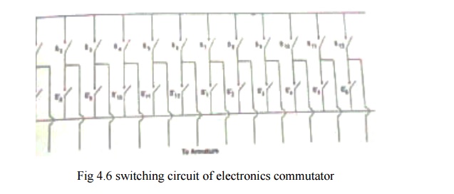
Thus by
operating the switch in a sequential manner it is possible to get a revolving
mmf in the air gap. The switches S1 to S12 and SŌĆś1 to SŌĆś12 can be replaced by
power electronic switching devices such as SCRŌĆśs MOSFETŌĆśs IGBTŌĆśs, power
transistor etc.
When
SCRŌĆśs are used suitable commutating circuit should be included. Depending upon
the type of forced commutated employed, each switch requires on or two SCRs and
other commutating devices. As number of devices is increased, the circuit
becomes cumbersome.
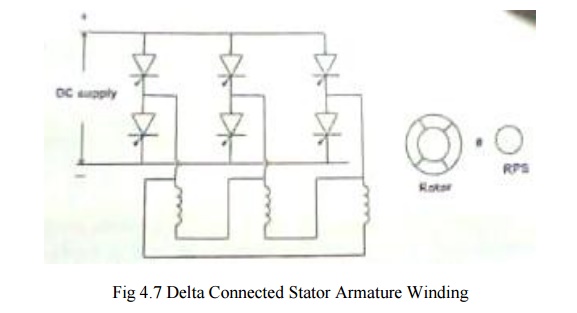
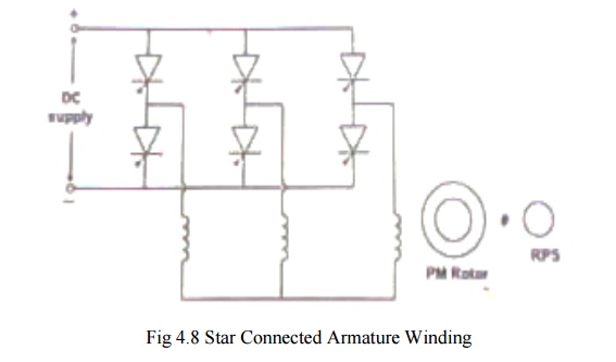
For
normal electronic commutator, usually six switching devices are employed. Then
the winding should have three tappingŌĆśs. Therefore the winding can be connected
either in star or in delta.
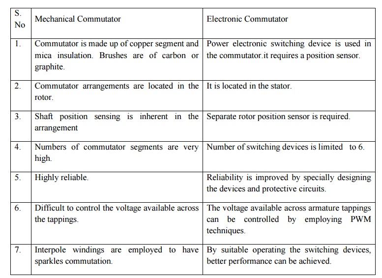
8. Comparison between mechanical
Commutator and brushes and Electronic Commutator
Related Topics