Chapter: Mechanical and Electrical : Power Plant Engineering : Coal Based Thermal Power Plants
Compare Impulse and reaction turbines
Compare Impulse and reaction turbines
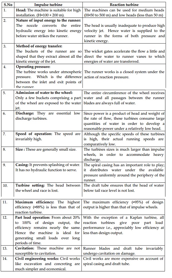
S.No Impulse turbine
1. Head:
The machine is suitable for high installation. (H=100 + 200 m).
2. Nature of input energy to the runner:
The nozzle converts the entire hydraulic energy into kinetic energy before water strikes the runner.
3. Method of energy transfer:
The buckets of the runner are so shaped that they extract almost all the kinetic energy of the jet.
4. Operating pressure:
The turbine works under atmospheric pressure. Which is the difference between the inlet and exit points of the runner.
5. Admission of water to the wheel:
Only a few buckets comprising a part of the wheel are exposed to the water jet.
6. Discharge: They are essential low discharge turbines.
7. Speed of operation: The speed are invariably high.
8. Size : These are generally small size.
9. Casing: It prevents splashing of water. It has no hydraulic function to serve.
10. Turbine setting: The head between the wheel and race is lost.
11. Maximum efficiency: The highest efficiency (=88%) is less than that of reaction turbine.
12. Part load operation: From about 20% to 100% of design output, the efficiency remains nearly the same. Hence the machine is ideal for generating small loads over long periods of time.
13. Cavitation: These machine are not susceptible to cavitation.
14. Civil engineering works: Civil works like excavation and concreting are much simpler and economical.
S.No Reaction turbine
1. Reaction turbine The machines can be used for medium heads (H=50 to 500 m) and low heads (less than 50 m)
2. The head is usually inadequate to produce high velocity jet. Hence water is supplied to the runner in the forms of both pressure and kinetic energy.
3. The wicket gates accelerate the flow a little and direct the water to runner vanes to which energies of water are transferred.
4. The runner works is a closed system under the action of reaction pressure.
5. The entire circumference of the wheel receives water and all passages between the runner blades are always full of water.
6. Since power is a product of head and weight of the rate of flow, these turbines consume large quantities of water in order to develop a reasonable power under a relatively low head.
7. Although the specific speeds of these turbines is high, their actual running speeds are comparatively low.
8. The turbines sizes is much larger than impulse wheels, in order to accommodate heavy discharge.
9. The spiral casing has an important role to play; it distributes water under the available pressure uniformly around the periphery of the runner.
10. The draft tube ensures that the head of water below tail race level is not lost.
11. The maximum efficiency (=95%) of design output is higher than that of impulse wheels.
12. With the exception of a Kaplan turbine, all reaction turbines give poor part load performance i.e., appreciably low efficiency at less than design output.
13. Runner blades and draft tube invariably undergo cavitation on damage.
14. Civil works are more expensive on account of spiral casing and draft tube.
Related Topics