Chapter: Electronic Circuits : Oscillators
Colpitts Oscillator Circuit
Colpitts Oscillator Circuit
The Colpitts oscillator uses a capacitor
voltage divider as its feedback source.
The two capacitors, C1 and C2 are placed across
a common inductor, L as shown so that C1, C2 and L forms the tuned tank circuit
the same as for the Hartley oscillator circuit.
The advantage of this type of tank circuit
configuration is that with less self and mutual inductance in the tank circuit,
frequency stability is improved along with a more simple design. As with the
Hartley oscillator, the Colpitts oscillator uses a single stage bipolar
transistor amplifier as the gain element which produces a sinusoidal output.
Consider the circuit below.
1. Basic
Colpitts Oscillator Circuit
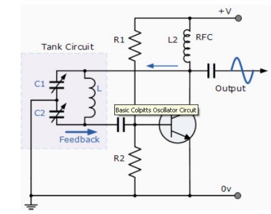
The transistor amplifiers emitter is connected
to the junction of capacitors, C1 and C2 which are connected in series and act
as a simple voltage divider. When the power supply is firstly applied,
capacitors C1 and C2 charge up and then discharge through the coil L. The
oscillations across the capacitors are applied to the base-emitter junction and
appear in the amplified at the collector output. The amount of feedback depends
on the values of C1 and C2 with the smaller the values of C the greater will be
the feedback.
The required external phase shift is obtained
in a similar manner to that in the Hartley oscillator circuit with the required
positive feedback obtained for sustained un-damped oscillations. The amount of
feedback is determined by the ratio of C1 and C2 which are generally
"ganged" together to provide a constant amount of feedback so as one
is adjusted the other automatically follows.
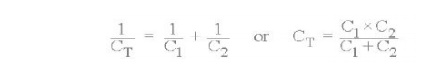
The frequency of oscillations for a Colpitts
oscillator is determined by the resonant frequency of the LC tank circuit and
is given as:

where CT is the capacitance of C1
and C2 connected in series and is given as:.
The configuration
of the transistor
amplifier is of a Common Emitter
Amplifier with the output signal 180o out of phase with regards to
the input signal. The additional 180o phase shift require for
oscillation is achieved by the fact that the two capacitors are connected
together in series but in parallel with the inductive coil resulting in overall
phase shift of the circuit being zero or 360o. Resistors, R1 and R2
provide the usual stabilizing DC bias for the transistor in the normal manner
while the capacitor acts as a DC-blocking capacitors. The radio-frequency choke
(RFC) is used to provide a high reactance (ideally open circuit) at the
frequency of oscillation, ( ƒr ) and a low resistance at DC.
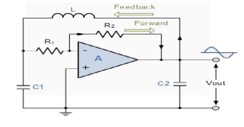
2. Colpitts Oscillator using an Op-amp
As well as using a bipolar junction transistor
(BJT) as the amplifiers active stage of the Colpitts oscillator, we can also
use either a field effect transistor, (FET) or an operational amplifier,
(op-amp). The operation of an Op-amp
Colpitts Oscillator is exactly the same as for the transistorised version
with the frequency of operation calculated in the same manner. Consider the
circuit below.
3. Colpitts Oscillator Op-amp Circuit
The advantages of the Colpitts Oscillatorover
the Hartley oscillators are that the Colpitts oscillator produces a more purer
sinusoidal waveform due to the low impedance paths of the capacitors at high
frequencies. Also due to these capacitive reactance properties the Colpitts
oscillator can operate at very high frequencies into the microwave region.
Related Topics