Chapter: Mechanical : Metrology and Measurements : Laser Metrology
Co-Ordinate Measuring Machines
CO-ORDINATE MEASURING
MACHINES
Measuring machines are used for
measurement of length over the outer surfaces of a length bar or any other long
member. The member may be either rounded or flat and parallel. It is more
useful and advantageous than vernier calipers, micrometer, screw gauges etc.
the measuring machines are generally universal character and can be used for
works of varied nature. The co-ordinate measuring machine is used for contact
inspection of parts. When used for computer-integrated manufacturing these
machines are controlled by computer numerical control. General software is
provided for reverse engineering complex shaped objects. The component is
digitized using CNC, CMM and it is then converted into a computer model which
gives the two surface of the component. These advances include for automatic
work part alignment on the table. Savings in inspection 5 to 10 percent of the
time is required on a CMM compared to manual inspection methods.
Types of Measuring
Machines
1. Length
bar measuring machine.
2. Newall
measuring machine.
3. Universal
measuring machine.
4. Co-ordinate
measuring machine.
5. Computer
controlled co-ordinate measuring machine.
Constructions of CMM
Co-ordinate measuring machines are very
useful for three dimensional measurements. These machines have movements in
X-Y-Z co-ordinate, controlled and measured easily by using touch probes. These
measurements can be made by positioning the probe by hand, or automatically in
more expensive machines. Reasonable accuracies are 5 micro in. or 1 micrometer.
The method these machines work on is measurement of the position of the probe
using linear position sensors. These are based on moiré fringe patterns (also
used in other systems). Transducer is provided in tilt directions for giving
digital display and senses positive and negative direction.
Types of CMM
(i) Cantilever type
The cantilever type is very easy to load
and unload, but mechanical error takes place because of sag or deflection in
Y-axis.
(ii)
Bridge type
Bridge
type is more difficult to load but less sensitive to mechanical errors.
(iii) Horizontal boring Mill type
This is best suited for large heavy work
pieces.
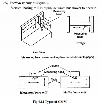
Fig 4.12 Types of CMM
Working
Principle
CMM is used for measuring the distance
between two holes. The work piece is clamped to the worktable and aligned for
three measuring slides x, y and z. The measuring head provides a taper probe
tip which is seated in first datum hole and the position of probe digital read
out is set to zero. The probe is then moved to successive holes, the read out
represent the co-ordinate part print hole location with respect to the datum
hole. Automatic recording and data processing units are provided to carry out
complex geometric and statistical analysis. Special co-ordinate measuring
machines are provided both linear and rotary axes. This can measure various
features of parts like cone, cylinder and hemisphere. The prime advantage of
co-ordinate measuring machine is the quicker inspection and accurate
measurements.
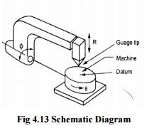
Fig 4.13 Schematic
Diagram
Causes of Errors in CMM
1)
The table and probes are in imperfect
alignment. The probes may have a degree of run out and move up and down in the
Z-axis may cause perpendicularity errors. So CMM should be calibrated with
master plates before using the machine.
2) Dimensional
errors of a CMM is influenced by
·
Straightness and perpendicularity of the
guide ways.
·
Scale division and adjustment.
·
Probe length.
·
Probe system calibration, repeatability,
zero point setting and reversal error.
·
Error due to digitization.
·
Environment
3)
Other errors can be controlled by the
manufacture and minimized by the measuring software. The length of the probe
should be minimum to reduce deflection.
4)
The weight of the work piece may change
the geometry of the guide ways and therefore, the work piece must not exceed
maximum weight.
5)
Variation in temperature of CMM,
specimen and measuring lab influence the uncertainly of measurements.
6)
Translation errors occur from error in
the scale division and error in straightness perpendicular to the corresponding
axis direction.
7) Perpendicularity
error occurs if three axes are not orthogonal.
5 Calibration
of Three Co-Ordinate Measuring Machine
The optical set up for the V calibration is shown in
figure
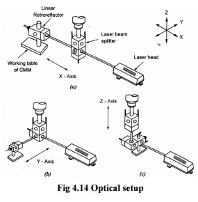
The laser head is mounted on the tripod stand and
its height is adjusted corresponding to the working table of CMM. The
interferometer contains a polarized beam splitter which reflects F1 component
of the laser beam and the F2 Component parts through. The retro reflector is a
polished trihedral glass prism. It reflects the laser beam back along a line
parallel to the original beam by twice the distance. For distance measurement
the F1 and F2 beams that leave the laser head are aimed at the interferometer
which splits F1 and F2 via polarizing beaming splitter. Component F1 becomes
the fixed distance path and F2 is sent to a target which reflects it back to
the interferometer. Relative motion between the interferometer and the remote
retro reflector causes a Dopper shift in the returned frequency. Therefore the
laser head sees a frequency difference given by F1-F2 ± ΔF2. The-F2 ±F1ΔF2
signal that is external interferometer is compared in the measurement display
unit to the reference signal. The difference ΔF2 is related to microscope of
CMM is set at zero and the laser display unit is also set at zero. The CMM
microscope is then set at the following points and the display units are
noted.1 to 10mm, every mm and 10 to 200mm, in steps of 10mm. The accuracy of
linear measurements is affected by changes in air temperature, pressure and
humidity.
Performance of CMM
·
Geometrical accuracies such as positioning accuracy, Straightness and
Squareness.
Related Topics