Chapter: Linear Integrated Ciruits : Application of ICs
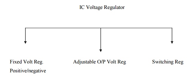
Classifications of IC voltage regulators
Classifications of IC voltage
regulators:
·
Fixed & Adjustable output Voltage Regulators
are known as Linear Regulator.
·
A series pass transistor is used and it operates
always in its active region. Switching Regulator:
1.
Series Pass Transistor acts as a switch.
2.
The amount of power dissipation in it decreases considerably.
3.
Power saving result is higher efficiency compared
to that of linear.
4.
Adjustable Voltage Regulator:
Advantages
of Adjustable Voltage Regulator over fixed voltage regulator are,
1.
Adjustable output voltage from 1.2v to 57 v
2.
Output current 0.10 to 1.5 A
3.
Better load & line regulation
4.
Improved overload protection
5.
Improved reliability under the 100% thermal
overloading
Adjustable
Positive Voltage Regulator (LM317):
·
LM317 series adjustable 3 terminal positive voltage
regulator, the three terminals are Vin, Vout& adjustment (ADJ).
·
LM317 requires only 2 external resistors to set the
output voltage.
·
LM317 produces a voltage of 1.25v between its
output & adjustment terminals. This voltage is called as Vref.
·
Vref (Reference Voltage) is a constant,
hence current I1 flows through R1 will also be constant.
Because resistor R1 sets current I1. It is called
―current set‖ or ―program resistor‖.
·
Resistor R2
is called as ―Output set‖ resistors, hence current through this resistor is the
sum of I1
·
LM317 is designed in such as that Iadj is very
small & constant with changes in line voltage & load current.
·
The
output voltage Vo is, Vo=R1I1+(I1+Iadj)R2
------------- (1)
Where I1=
Vref/R1
Vo
=(Vref/R1)R1 + Vref/R1 +
Iadj R2
= Vref
+ (Vref/R1)R2 + Iadj R2
Vo
= Vref [1 + R2/R1] + Iadj R2------------- (2)
R1
= Current (I1) set resistor
R2
= output (Vo) set resistor
Vref
= 1.25v which is a constant voltage between output and ADJ terminals.
·
Current Iadj is very small. Therefore
the second term in (2) can be neglected.
·
Thus the final expression for the output voltage is
given by
Vo=
1.25v[1 + R2/R1]-------------- (3)
Eqn (3)
indicates that we can vary the output voltage by varying the resistance R2. The
value of R1 is normally kept constant at 240 ohms for all practical
applications.
Practical
Regulator using LM317:
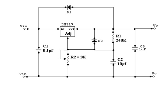
·
If LM317 is far away from the input power supply,
then 0.1μf disc type or 1μf tantalum capacitor should be used at the input of
LM317.
·
The output capacitor Co is optional. Co should be
in the range of 1 to 1000μf.
·
The adjustment terminal is bypassed with a
capacitor C2 this will improve the ripple rejection ratio as high as 80 dB is
obtainable at any output level.
·
When the filter capacitor is used, it is necessary
to use the protective diodes.
·
These diodes do not allow the capacitor C2 to
discharge through the low current point of the regulator.
·
These diodes are required only for high output
voltages (above 25v) & for higher values of output capacitance 25μf and
above.
Related Topics