Chapter: Civil : Repair and Rehabilitation of Structures : Serviceability and Durability of Concrete
Classification of cracks and Cracking in Concrete
Cracking
Cracking will occur whenever the
tensile strain, to which concrete is subjected, exceeds the tensile strain
capacity of the concrete. The tensile strain capacity of concrete varies with
age and with the rate of application of strain.
Classification of cracks
It may be classified in terms of their effects:
� Those
cracks which indicate immediate structural distress
� Those
cracks which may lead in the long run to a reduction of safety, through
corrosion of steel
� Cracks
which lead to malfunction of the structure, as evidenced by leakage, sound
transfer, damage to finishes and unsatisfactory operation of windows and doors
� Cracks
which are aesthetically unacceptable
Class I-Cracks leading to Structural Failure
Little difficulty arises in
relation to this class. Those cracks that indicate that failure is near and
that margin of safety are seriously reduced, may have formed in concrete, which
was expected by the designer, to carry load in its un cracked condition .Such
cracks are necessarily wide, and may lead to the detachment of parts of the
structure.
Class II Cracks causing Corrosion
There is no unique relationship
between crack width and the onset of corrosion. Part of the difficulty arises
from the nature of cracks themselves. For flexural members, many cracks taper
from a certain width at the surface of the concrete, the near zero width at the
steel-concrete interface. However, flexural cracks that are controlled by the
overall depth of the beam are not of the tapered shape, and it is likely that
cracks due to temperature and shrinkage are nearer to being parallel sided. It
has been assumed for many years that, since wider cracks would give easier
access to aggressive substances, corrosion could be controlled by controlling
crack widths and that permissible widths should be a function of how aggressive
the environment was many complicated formulas for the calculation of crack
widths in flexural members have been devised with the object of controlling
corrosion. But extensive tests on beams in which the cracks are normal to the
axis of the bars show evidence of any relationship between corrosion damage and
crack width.
When cracks run along a bar, much
more of the bar is in an exposed position, and it might be expected that there
would be a closer relationship between crack width and corrosion in this
situation. There is a little evidence however, that cracks whether transverse
to the bars or running along the bars, pose any create risk of increased
corrosion, if they are less than 0.3mm in width.
Some cracks, which are parallel
to a bar, may have been caused by the corrosion of that bar. These cracks will
widen as corrosion proceeds, and will eventually lead to spalling and exposure
of the corroded bar. A crack of any width, which is judged to be brought about
by corrosion, is an indication of a deteriorating structure, and therefore no
minimum width, below which the crack is not significant, can be set. A crack
that indicates the corrosion of the bar is actually showing that the corrosion
will continue, unless positive measures are taken. Merely filling the crack
will not achieve the result.
Class III-cracks affecting Function
The cracks in this class, which
have the most serious consequences are those that allow liquid-retailing
structures to leak, or that occur in roofs or other structures, intended to be
waterproof. BS 8007 prescribes limiting crack widths and details methods of
predicting the widths. The maximum design surface crack width, for direct tension
and flexure or restrained temperature and moisture effects are:
Severe or very severe exposure-0.2mm
There are only limited test data
available on what constitutes the limiting crack, for preventing leakage. Flow
through a parallel-sided smooth crack, can be calculated in terms of head,
crack width, crack length and fluid viscosity. The difficulty with concrete is
that the cracks are not smooth or parallel-sided.
Class IV-cracks affecting appearance
For class 4cracks,it has been
suggested that crack widths up to 0.3mm in width are acceptable aesthetically,
but there are no good guidelines. Various attempts have been made to establish
what constitutes an acceptable crack on an aesthetic basis, but in the end,
there is no rational basis for aesthetic decisions. The aesthetic objection to
cracks may be summarized as:
�
Cracks cause alarm about the safety of the
structure
�
Cracks lower the visual acceptance of the
structure (a) by modifying surface textures and damaging the visual effect
intended by the designer and (b) by giving an appearance of cheapness or bad
building.
Causes of cracking:
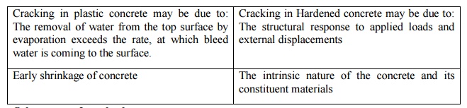
Other
types of cracks due to:
Delayed
curing
Formwork
movement
Excess
vibration
Sub
grade settlement
Finishing
Early
frost damage
Unsound
materials
Long-term
drying shrinkage
Related Topics