Chapter: Mechanical and Electrical : Power Plant Engineering : Coal Based Thermal Power Plants
Classification of Fluidized Bed Combustion
Classification of Fluidized Bed combustion and Bubbling
a)fluidized
Bed Combustor
b)
Circulating fluidized bed combustor
Classification
of Fluidized Bed Combustion:
1. Atmospheric fluidized Bed Combustion
(AFBC)
a.
Bubbling
fluidized bed combustors
b.
Circulating
fluidized
2.Pressurized
Fluidized Bed Combustin (PFBC)
Atmospheric
Fluidized Bed Combustion (AFBC)
Bubbling
fluidized bed combustor
A typical
BFB arrangement is illustrated schematically in figure. Fuel and sorbent are
introduced either above or below the fluidized bed. (Overbed feed is
illustrated.) The bed consisting of about 97% limestone or inert material and
3% burning fuel, is suspended by hot primary air entering the bottom of the
combustion chamber. The bed temperature is controlled by heat transfer tubes
immersed in the bed and by varying the quantity of coal in the bed. As the coal
particle size decreases, as a result of either combustion or attrition, the
particles are elutriated from the bed and carried out the combustor. A portion
of the particles elutriated from the bed are collected by a cyclone (or
multiclone) collector down-stream of the convection pass and returned to the
bed to improve combustion efficiency.
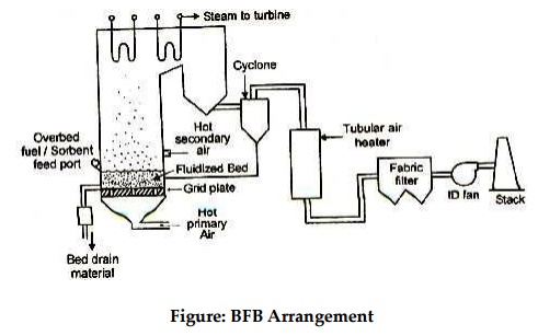
Figure:
BFB Arrangement
Secondary air can be added above the bed to improve
combustion efficiency and to achieve staged combustion , thus lowering NOx
emissions. Most of the early BFBs used tubular air heaters to minimize air
leakage that could occur as a result of relatively high primary air pressures
required to suspend the bed. Recent designs have included regenerative type air
heaters.
Circulating
fluidized bed combustor
A typical CFB arrangement is illustrated schematically in
figure. In a CFB, primary air is introduced into the lower portion of the
combustor, where the heavy bed material is fluidized and retained. The upper
portion of the combustor contains the less dense material that is entrained
from the bed. Secondary air typically is introduced at higher levels in the
combustor to ensure complete combustion and to reduce NOx emissions.
The combustion gas generated in the combustor flows upward
with a considerable portion of the solids inventory entrained. These entrained
solids are separated from the combustion gas in hot cyclone-type dust
collectors or in mechanical particle separators, and are continuously returned
to the combustion chamber by a recycle loop.
The
combustion chamber of a CFB unit for utility applications generally consists of
membrane-type welded water walls to provide most of the evaporative boiler
surface. The lower third of the combustor is refractory lined to protect the
water walls from erosion in the high-velocity dense bed region. Several CFB
design offer external heat exchangers, which are unfired dense BFB units that
extract heat from the solids collected by the dust collectors before it is
returned to the combustor. The external heat exchangers are used to provide
additional evaporative heat transfer surface as well as superheat and reheat
surface, depending on the manufacturer’sdesign.
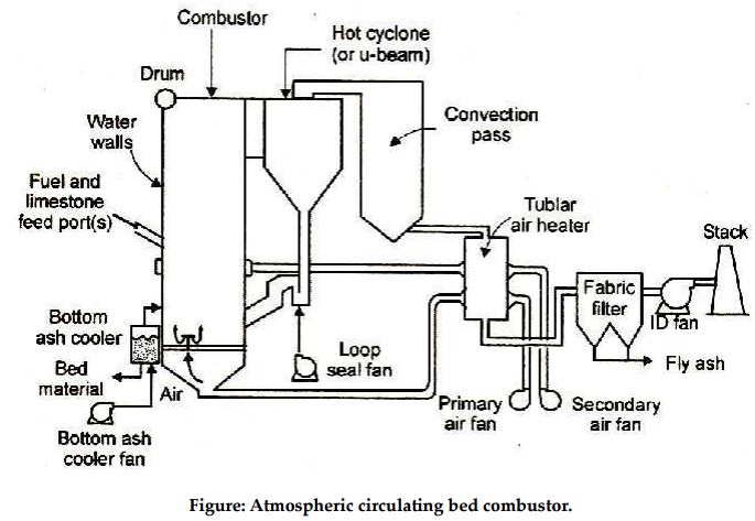
Figure: Atmospheric circulating bed
combustor.
The flue gas, after removal of more than 99% of the
entrained solids in the cyclone or particle separator, exists the cyclone or
separator to a convection pass. The convection pass designs are similar to
those used with unconvectional coal-fueled units, and contain economizer,
superheat, and reheat surface as required by the application.
Pressurized
fluidized Bed combustion
Pressurized
Fluidized Bed Combustion:
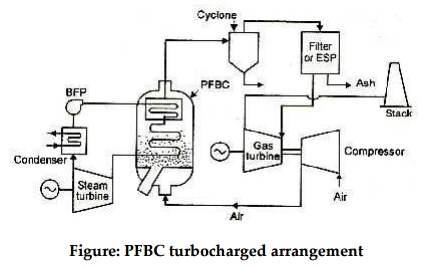
Figure: PFBC turbocharged arrangement
The PFBC unit is classified as either turbocharged or
combined cycle units. In turbocharged arrangements (figure) combustion gas from
the PEBC boiler is cooled to approximately 394°C and is used to drive a gas turbine.
The gas turbine drives an air compressor, and there is little, if any, net gas
turbine output. Electricity is produced by a turbine generator driven by steam
generated in the PFBC boiler.
In the
combined cycle arrangement (figure) 815°C to 871°C
combustion gas from the PFBC boiler is used to drive the gas turbine. About 20%
of the net plant electrical output is provided by the gas turbine. With this
arrangement, thermal efficiency 2 to 3 percentage points higher than with the
turbocharged cycle are feasible.
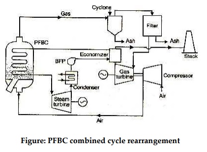
Figure: PFBC combined cycle
rearrangement
Related Topics