Chapter: civil : Applied Hydraulic Engineering: Pumps
Centrifugal Pumps
Centrifugal Pumps
These are so called because energy is imparted to the fluid by
centrifugal action of moving blades from the inner radius to the outer radius.
The main components of centrifugal pumps are (1) the impeller, (2) the casing
and (3) the drive shaft with gland and packing.
Additionally suction pipe with one way valve (foot valve) and
delivery pipe with delivery valve completes the system.
The liquid enters the eye of the impeller axially due to the
suction created by the impeller motion. The impeller blades guide the fluid and
impart momentum to the fluid, which increases the total head (or pressure) of
the fluid, causing the fluid to flow out.
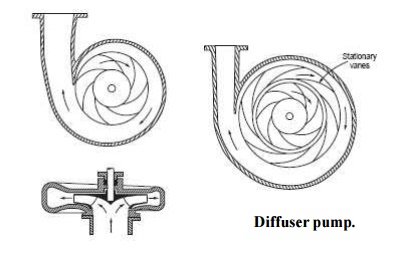
The fluid comes out at a high velocity which is not directly
usable. The casing can be of simple volute type or a diffuser can be used as
desired. The volute is a spiral casing of gradually increasing cross section. A
part of the kinetic energy in the fluid is converted to pressure in the casing.
Figure
shows a sectional view of the centrifugal pump.
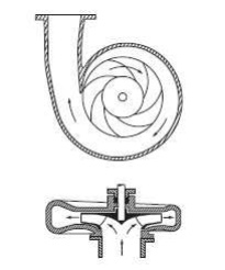
1 Volute type centrifugal
pump.
Gland and packing or so called stuffing box is used to reduce
leakage along the drive shaft. By the use of the volute only a small fraction
of the kinetic head can be recovered as useful static head.
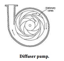
A
diffuser can diffuse the flow more efficiently and recover kinetic head as
useful static head. A view of such arrangement is shown in figure Diffuser pump
are also called as turbine pumps as these resembles Francis turbine with flow
direction reversed.
2
Impeller
The impeller consists of a disc with blades mounted
perpendicularly on its surface. The blades may of three different orientations.
These are
(i) Radial, (ii) Backward curved, and (iii) Forward
curved.
Backward
and forward refers to the direction of motion of the disc periphery. Of these
the most popular one is the backward curved type, due to its desirable characteristics,
which reference to the static head
developed and power
variation with flow rate.
A simple disc
with blades mounted perpendicularly on it is
called open impeller. If another
disc is used to cover the blades, this type is called shrouded impeller. This
is more popular with water pumps. Open impellers are well adopted for use with
dirty or water containing solids. The third type is just the blades spreading
out from the shaft.
These are used to pump slurries. Impellers may be of cast iron
or bronzes or steel or special alloys as required by the application. In order
to maintain constant radial velocity, the width of the impeller will be wider
at entrance and narrower at the exit. The blades are generally cast integral
with the disc. Recently even plastic material is used for the impeller. To
start delivery of the fluid the casing and impeller should be filled with the
fluid without any air pockets. This is called priming.
If air is present the there will be only compression and no
delivery of fluid. In order to release any air entrained an air valve is
generally provided
The one
way foot value keeps the suction line and the pump casing filled with water.
3 Classification
As already mentioned, centrifugal pumps may be classified in
several ways. On the basis of speed as low speed, medium speed and high speed
pumps.
On the basis of direction of flow of fluid, the classification
is radial flow, mixed flow and radial flow. On the basis of head pumps may be
classified as low head (10 m and below), medium head (10-50 m) and high head
pumps.
Single
entry type and double entry type is another classification. Double entry pumps
have blades on
both sides of
the impeller disc.
This leads to reduction in axial thrust and increase in flow for the
same speed and diameter.
When the
head required is high and which cannot
be developed by
a single impeller, multi
staging is used.
In deep well
submersible pumps the diameter is limited by the diameter of the
bore well casing. In this case multi stage pump becomes a must. In multi stage
pumps several impellers are mounted on the same shaft and the outlet flow of
one impeller is led to the inlet of the next impeller and so on. The total head
developed equals the sum of heads developed by all the stages.
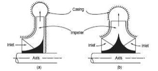
4 Single
and double entry pumps
Pumps may also be operated in parallel to obtain
large volumes of flow. The characteristics under series and parallel operations
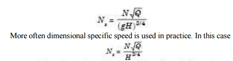
are discussed later in the chapter. The classification may also be based on the
specific speed of the pump. the dimensionless parameters have
been derived in the case of hydraulic machines. The same is also repeated in
example.
The
expression for the dimensionless specific speed is given in equation
5 Pressure Developed By
The Impeller
The
general arrangement of a centrifugal pump system is shown in Figure
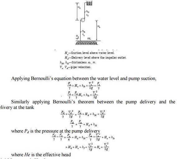
where He
is the effective head
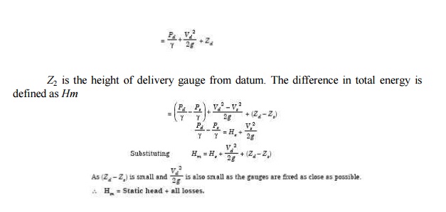
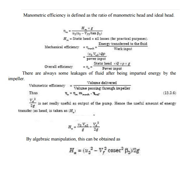
6 Manometric Head
The official code defines the head on the pump as the
difference in total energy heads at the suction and delivery flanges. This head
is defined as manometric head.
The total
energy at suction inlet (expressed as head of fluid)
F/r + V2/2g + Zs
where Zs
is the height of suction gauge from datum. The total energy at the delivery of
the pump
F/r + V2/2g + Zs
Z2 is the
height of delivery gauge from datum. The difference in total energy is defined
as Hm
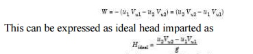
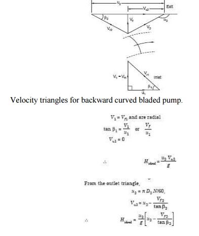
7 Energy Transfer By
Impeller
The
energy transfer is given by Euler Turbine equation applied to work absorbing
machines,
The
velocity diagrams at inlet and outlet of a backward curved vaned impeller is
shown in figure The inlet whirl is generally zero. There are no guide vanes at
inlet to impart whirl. So the inlet triangle is right angled.
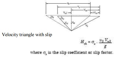
8 Slip and Slip Factor
In the analysis it is assumed that all the fluid between two
blade passages have the same velocity (both magnitude of direction). Actually
at the leading edge the pressure is higher and velocity is lower. On the
trailing edge the pressure is lower and the velocity is higher. This leads to a
circulation over the blades. Causing a non uniform velocity distribution.
The
average angle at which the fluid leaves the blade is less than the blades
angle. The result is a reduction in the exit whirl velocity Vu2. This is
illustrated in the following figure. The solid lines represent the velocity
diagram without slip. The angle ?2 is the
blade angle. The dotted lines represent the velocity diagram after slip. The
angle
?2? < ?2. It may
be seen that Vu2? < Vu2. The ratio Vu2?/Vu2
is known as slip factor. The result of the slip is that the energy transfer to
the fluid is less than the theoretical value.
9 Losses
in Centrifugal Pumps
Mainly
there are three specific losses which can be separately calculated. These are
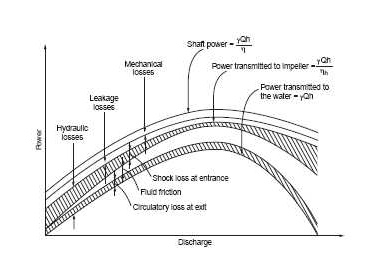
10 Losses in pump
(i) Mechanical friction losses between the fixed and
rotating parts in the bearings and gland and packing.
(ii)
Disc friction loss between the impeller surfaces and the fluid.
(iii)
Leakage and recirculation losses. The recirculation is along the clearance
between the impeller and the casing due to the pressure difference between the
hub and tip of the impeller. The various losses are indicated in figure.
11 Pump
Characteristics
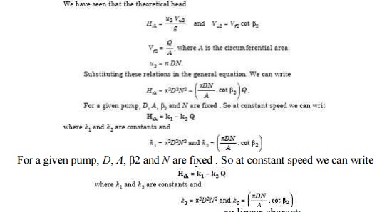
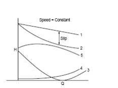
Hence at constant speed this leads to a drooping linear
characteristics for backward curved blading. This is shown by curve 1 in Figure
15.4.1. The slip causes drop in the head, which can be written as ? Vu2
u2/g. As flow increases this loss also increases.
Curve 2
shown the head after slip. The flow will enter without shock only at the design
flow rate. At other flow rates, the water will enter with shock causing losses.
This lose
can be expressed as hshock =
k3 (Qth - Q)2
The
reduced head after shock losses is shown in curve 5. The shock losses with flow
rate is shown by curve 3. The mechanical losses can be represented by hf = k4
Q2. The variation is shown by curve 4. With variation of speed the head
characteristic is shifted near paralley with the curve 5 shown in Figure.
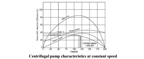
12 Characteristics of a
centrifugal pump
The
characteristic of a centrifugal pump at constant speed is shown in Figure. It
may be noted that the power increases and decreases after the rated capacity.
In this way the pump is self limiting in power and the choice of the motor is
made easy. The distance between the brake power and water power curves gives
the losses.
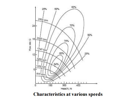
The
pump characteristics at various speeds including efficiency contours in shown
in Figure. Such a plot helps in the development of a pump, particularly in
specifying the head and flow rates.
Related Topics