Chapter: Embedded Systems Design : Design examples
Burglar alarm system
Embedded Systems Design example
Burglar alarm system
This example describes the design and development of an MC68008-based
burglar alarm with particular reference to the software and hardware debugging
techniques that were used. The design and debugging was performed without the
use of an emulator, the traditional development tool, and used cross-compilers
and evaluation boards instead. The design process was carefully controlled to
allow the gradual integra-tion of the system with one unknown at a time. The
decision process behind the compiler choice, the higher level software
development and testing, software porting, hardware testing and integration are
fully explained.
Design goals
The system under design was an MC68008-based intel-ligent burglar alarm
which scanned and analysed sensor in-puts to screen out transient and false
alarms. The basic hard-ware consisted of a processor, a 2k × 8 static RAM, a 32k × 8 EPROM and three octal latches
(74LS373) to provide 16 sensor and data inputs and 8 outputs.
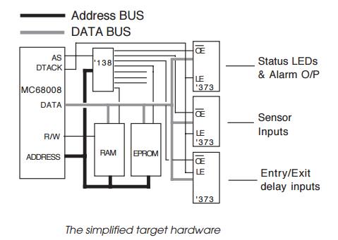
A 74LS138 was used to generate chip selects and output enables for the
memory chips and latches from three higher order address lines. Three lines
were left for future expansion. The sirens etc., were driven via 5 volt gate
power MOSFETs. The controlling software was written in C and controlled the
whole timing and response of the alarm system. Interrupts were not used and the
power on reset signal generated using a CR network and a Schmidt gate.
Development strategy
The normal approach would be to use an in-circuit emulator to debug the
software and target hardware, but it was decided at an early stage to develop
the system without using an emulator except as a last resort. The reasoning was
simple:
•
The unit was a replacement for a
current analogue system, and the physical dimensions of the case effec-tively
prevented the insertion of an emulation probe. In addition, the case location
was very inaccessible.
•
The hardware design was a minimum
system which relied on the MC68008 signals to generate the asynchro-nous
handshakes automatically, e.g. the address strobe is immediately routed back to
generate a DTACK signal. This configuration reduces the component count but any
erroneous accesses are not recognised. While these timings and techniques are
easy to use with a processor, the potential timing delays caused by an emulator
could cause problems which are exhibited when real silicon is used.
•
The software development was
performed in parallel with the hardware development and it was important that
the software was tested in as close an environment as possible to a debugged
target system early on in the design. While emulators can provide a simple
hardware platform, they can have difficulties in coping with power-up tests and
other critical functions.
The strategy was finally based on several policies:
•
At every stage, only one unknown
would be introduced to allow the fast and easy debugging of the system, e.g.
software modules were developed and tested on a known working hardware
platform, cross-compiled and tested on an evaluation board etc.
•
An evaluation board would be used
to provide a work-ing target system for the system software debugging. One of
the key strategies in this approach for the project was to ensure the closeness
of this environment to the target system.
•
Test modules would be written to
test hardware func-tionality of the target system, and these were tested on the
evaluation board.
•
The system software would only be
integrated on the target board if the test modules executed correctly.
Software development
The first step in the development of the software was to test the logic
and basic software design using a workstation. A UNIX workstation was initially
used and this allowed the bulk of the software to be generated, debugged and
functionally tested within a known working hardware environment, thus keeping
with the single unknown strategy. This restricts any new unknown software or
hardware to a single component and so makes debugging easier to perform.
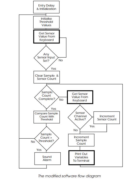
Sensor inputs were simulated using getchar() to obtain values from a keyboard, and by using the multitasking
signalling available with a UNIX environment. As a result, the keyboard could
be used to input values with the hexadecimal value representing the input port
value. Outputs were simu-lated using a similar technique using printf() to display the information on the screen. Constants for software delays
etc., were defined using #define C
pre-processor statements to allow their easy modification. While the system
could not test the software in real-time, it does provide functional and
logical testing.
While it is easy to use the getchar() routine to gener-ate an integer value based on the ASCII value of the
key that has been pressed, there are some difficulties. The first problem that
was encountered was that the UNIX system uses buffered input for the keyboard.
This meant that the return key had to be pressed to signal the UNIX machine to
pass the data to the program. This initially caused a problem in that it
stopped the polling loop to wait for the keyboard every time it went round the
loop. As a result, the I/O simulation was not very good or representative.
In the end, two solutions were tried to improve the simulation. The
simplest one was to use the waiting as an aid to testing the software. By
having to press the return key, the execution of the polling loop could be
brought under the user’s control and by printing out the sample and sensor
count variables, it was possible to step through each loop individu-ally. By
effectively executing discrete polling loops and have the option of simulating
a sensor input by pressing a key before pressing return, other factors like the
threshold values and the disabling of faulty sensors could be exercised.
The more complex solution was to use the UNIX multitasking and
signalling facilities to set-up a second task to generate simple messages to
simulate the keyboard input. While this allowed different sensor patterns to be
sent to simulate various false triggering sequences without having the chore of
having to calculate the key sequences needed from the keyboard, it did not
offer much more than that offered by the simple solution.
The actual machine used for this was an OPUS personal mainframe based on
a MC88100 RISC processor running at 25 MHz and executing UNIX System V/88. The
reasons behind this decision were many:
•
It provided an extremely fast
system, which dramati-cally reduced the amount of time spent in compilation and
development.
•
The ease of transferring software
source to other sys-tems for cross-compilation. The OPUS system can di-rectly
read and write MS-DOS files and switch from the UNIX to PC environment at a
keystroke.
•
The use of a UNIX- based C
compiler, along with other utilities such as lint, was perceived to provide a
more standard C source than is offered by other compilers.
This was deemed important to prevent problems when cross-compiling.
Typical errors that have been encountered in the past are: byte ordering,
variable storage sizes, array and variable initialisation assumed availability
of special library routines etc.
Cross-compilation and code generation
Three MC68000 compilation environments were avail-able: the first was a
UNIX C compiler running on a VMEbus system, the second was a PC-based
cross-compiler supplied with the Motorola MC68020 evaluation board, while a
third option of another PC-based cross compiler was a possibility.
The criteria for choosing the cross-compilation development were:
•
The ease of modifying run-time
libraries to execute standalone on the MC68020 evaluation board and, fi-nally
the target system.
•
The quality of code produced.
The second option was chosen primarily for the ease with which the
run-time libraries could be modified. As stand-ard, full run-time support was
available for the evaluation board, and these modules, including the
all-important initiali-sation routines, were supplied in assembler source and
are very easy to modify. Although the code quality was not as good as the other
options, it was adequate for the design and the advantage of immediate support
for the software testing on the evaluation board more than compensated. This
support fitted in well with the concept of introducing only a single unknown.
If the software can be tested in as close an environment as possible to
the target, any difficulties should lie with the hardware design. With this
design, the only differences be-tween the target system configuration and the
evaluation board is a different memory map. Therefore, by testing the software
on an evaluation board, one of the unknowns can be removed when the software is
integrated with the target sys-tem. If the run-time libraries are already
available, this further reduces the unknowns to that of just the system
software.
The C source was then transferred to a PC for cross-compilation. The
target system was a Flight MC68020 evalua-tion board which provides a known
working MC68xxx envi-ronment and an on-board debugger. The code was
cross-compiled, downloaded via a serial link and tested again.
The testing was done in two stages: the first simply ran the software
that had been developed using the OPUS system without modifying the code. This
involved using the built-in getchar() system
calls and so on within the Flight board debugger. It is at this point that any differences between the C
compilers would be found such as array initialisation, bit and byte alignment
etc. It is these differences that can prevent software being ported from one
system to another. These tests provided further confidence in the software and
its functional-ity before further modification.
The second stage was to replace these calls by a pointer to a memory
location. This value would be changed through the use of the onboard debugger.
The evaluation board abort button is pressed to stop the program execution and
invoke the debugger. The corresponding memory location is modified and the
program execution restarted. At this point, the soft-ware is virtually running
as expected on the target system. All that remains to do is to take into
account the target hardware memory map and initialisation.
Porting to the final target system
The next stage involved porting the software to the final target
configuration. These routines allocate the program and stack memory, initialise
pointers etc., and define the sensor and display locations within the memory
map. All diagnostic I/O calls were removed. The cross-compiler used supplies a
start-up assembly file which performs these tasks. This file was modified and
the code recompiled all ready for testing.
Generation of test modules
Although the target hardware design was relatively simple, it was
thought prudent to generate some test modules which would exercise the memory
and indicate the success by lighting simple status LEDs. Although much simpler
than the controlling software, these go-nogo tests were developed us-ing the
same approach: written and tested on the evaluation board, changed to reflect
the target configuration and then blown into EPROM.
The aim of these tests was to prove that the hardware functioned
correctly: the critical operations that were tested included power-up reset and
initialisation, reading and writ-ing to the I/O functions, and exercising the
memory.
These routines were written in assembler and initially tested using the
Microtec Xray debugger and simulator before downloading to the Flight board for
final testing.
Target hardware testing
After checking the wiring, the test module EPROM was installed and the
target powered up. Either the system would work or not. Fortunately, it did!
With the hardware capable of accessing memory, reading and writing to the I/O
ports, the next stage was to install the final software.
While the system software logically functioned, there were some timing
problems associated with the software tim-ing loops which controlled the sample
window, entry/exit time delays and alarm duration. These errors were introduced
as a direct result of the software methodology chosen: the delay values would
obviously change depending on the hardware environment, and while the values
were defined using #define
pre-processor statements and were adjusted to reflect the processing power
available, they were inaccurate. To solve this problem, some additional test
modules were written, and by using trial and error, the correct values were
derived. The system software was modified and installed.
Future techniques
The software loop problem could have been solved if an MC68000 software
simulator had been used to execute, test and time the relevant software loops.
This would have saved a day’s work.
If a hardware simulator had been available, it could have tested the
hardware design and provided additional confi-dence that it was going to work.
Relevance to more complex designs
The example described is relatively simple but many of the techniques
used are extremely relevant to more complex designs. The fundamental aim of a
test and development methodology, which restricts the introduction of untested
software or hardware to a single item, is a good practice and of benefit to the
design and implementation of any system, even those that use emulation early on
in the design cycle.
The use of evaluation boards or even standalone VME or Multibus II
boards can be of benefit for complex designs. The amount of benefit is
dependent of the closeness of the evalua-tion board hardware to the target
system. If this design had needed to use two serial ports, timers and parallel
I/O, it is likely that an emulator would still not have been used pro-vided a
ready built board was available which used the same peripheral devices as the
target hardware. The low level soft-ware drivers for the peripherals could be
tested on the evalu-ation board and these incorporated into the target test
modules for hardware testing.
There are times, however, when a design must be tested and an emulator
is simply not available. This scenario occurs when designing with a processor
at a very early stage of product life. There is inevitably a delay between the
appear-ance of working silicon and instrumentation support. During this period,
similar techniques to those described are used and a logic analyser used
instead of an emulator to provide instru-mentation support, in case of
problems. If the processor is a new generation within an existing family,
previous members can be used to provide an interim target for some software
testing. If the design involves a completely new processor, similar techniques
can be applied, except at some point un-tested software must be run on untested
hardware.
It is to prevent this integration of two unknowns that simulation
software to either simulate and test software, hard-ware or both can play a
critical part in the development process.
The need for emulation
Even using the described techniques, it cannot be stated that there will
never be a need for additional help. There will be times when instrumentation,
such as emulation and logic analysis, is necessary to resolve problems within a
design quickly. Timing and intermittent problems cannot be easily solved
without access to further information about the proces-sor and other system
signals. Even so, the recognition of a potential problem source such as a
specific software module or hardware allows a more constructive use and a
speedier reso-lution. The adoption of a methodical design approach and the use
of ready built boards as test vehicles may, at best, remove the need for
emulation and, at worst, reduce the amount of time debugging the system.
Related Topics