Chapter: Basic Electrical and Electronics Engineering : Digital Electronics
Binary Adder and Subtractor
The Binary Adder
Another common and very useful combinational logic circuit which
can be constructed using just a few basic logic gates and adds together binary
numbers is the Binary Adder circuit. The Binary Adder is made up from standard
AND and Ex-OR gates and allow us to "add" together single bit binary
numbers, a and b to produce two outputs, the SUM of the addition and a CARRY
called the Carry-out, ( Cout ) bit. One of the main uses for the Binary Adder
is in arithmetic and counting circuits.
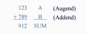
Consider the addition of two denary (base 10) numbers below.
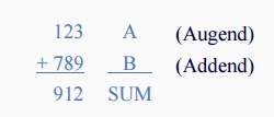
Each column is added together starting from the right hand side
and each digit has a weighted value depending upon its position in the columns.
As each column is added together a carry is generated if the result is greater
or equal to ten, the base number. This carry is then added to the result of the
addition of the next column to the left and so on, simple school math's
addition. The adding of binary numbers is basically the same as that of adding
decimal numbers but this time a carry is only generated when the result in any
column is greater or equal to "2", the base number of binary.
Binary Addition
Binary Addition follows the same basic rules as for the denary
addition above except in binary there are only two digits and the largest digit
is "1", so any "SUM" greater than 1 will result in a
"CARRY". This carry 1 is passed over to the next column for addition
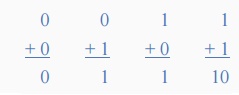
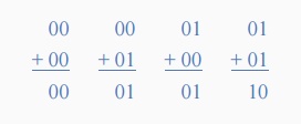
and so on. Consider the single bit addition below.
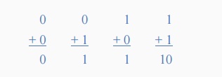
The single bits are added together and "0 + 0",
"0 + 1", or "1 + 0" results in a sum of "0" or
"1" until you get to "1 + 1" then the sum is equal to
"2". For a simple 1-bit addition problem like this, the resulting
carry bit could be ignored which would result in an output truth table
resembling that of an Ex-OR Gate as seen in the Logic Gates section and whose
result is the sum of the two bits but without the carry. An Ex-OR gate only
produces an output "1" when either input is at logic "1",
but not both. However, all microprocessors and electronic calculators require
the carry bit to correctly calculate the equations so we need to rewrite them
to include 2 bits of output data as shown below.
From the above equations we know that an Ex-OR gate will only
produce an output "1" when "EITHER" input is at logic
"1", so we need an additional output to produce a carry output,
"1" when "BOTH" inputs "A" and "B" are
at logic "1" and a standard AND Gate fits the bill nicely. By
combining the Ex-OR gate with the AND gate results in a simple digital binary
adder circuit known commonly as the "Half Adder" circuit.
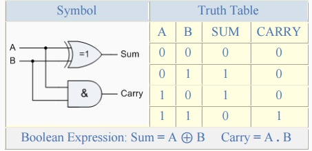
The Half Adder Circuit
1-bit Adder with Carry-Out
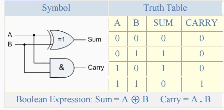
From the truth table we can see that the SUM (S) output is the
result of the Ex-OR gate and the Carry-out (Cout) is the result of the AND
gate. One major disadvantage of the Half Adder circuit when used as a binary
adder, is that there is no provision for a "Carry-in" from the
previous circuit when adding together multiple data bits. For example, suppose
we want to add together two 8-bit bytes of data, any resulting carry bit would
need to be able to "ripple" or move across the bit patterns starting
from the least significant bit (LSB). The most complicated operation the half
adder can do is "1 + 1" but as the half adder has no carry input the
resultant added value would be incorrect. One simple way to overcome this
problem is to use a Full Adder type binary adder circuit.
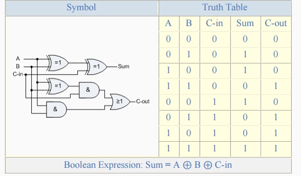
The Full Adder Circuit
The main difference between the Full Adder and the previous seen
Half Adder is that a full adder has three inputs, the same two single bit
binary inputs A and B as before plus an additional Carry-In (C-in) input as
shown below.
Full Adder with Carry-In
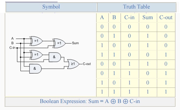
The 1-bit Full Adder circuit above is basically two half adders
connected together and consists of three Ex-OR gates, two AND gates and an OR
gate, six logic gates in total. The truth table for the full adder includes an
additional column to take into account the Carry-in input as well as the summed
output and carry-output. 4-bit full adder circuits are available as standard IC
packages in the form of the TTL 74LS83 or the 74LS283 which can add together
two 4-bit binary numbers and generate a SUM and a CARRY output. But what if we
wanted to add together two n-bit numbers, then n 1-bit full adders need to be
connected together to produce what is known as the Ripple Carry Adder.
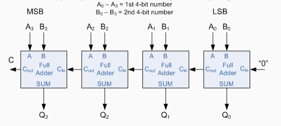
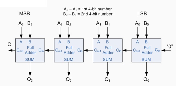
The 4-bit Binary Adder
The Ripple Carry Binary Adder is simply n, full adders cascaded
together with each full adder represents a single weighted column in the long
addition with the carry signals producing a "ripple" effect through
the binary adder from right to left. For example, suppose we want to "add"
together two 4-bit numbers, the two outputs of the first full adder will
provide the first place digit sum of the addition plus a carry-out bit that
acts as the carry-in digit of the next binary adder. The second binary adder in
the chain also produces a summed output (the 2nd bit) plus another carry-out
bit and we can keep adding more full adders to the combination to add larger
numbers, linking the carry bit output from the first full binary adder to the
next full adder, and so forth. An example of a 4-bit adder is given below.
A 4-bit Binary Adder
One main disadvantage of "cascading" together 1-bit
binary adders to add large binary numbers is that if inputs A and B change, the
sum at its output will not be valid until any carry-input has "rippled"
through every full adder in the chain.
Consequently, there will be a finite delay before the output of
a adder responds to a change in its inputs resulting in the accumulated delay
especially in large multi-bit binary adders becoming prohibitively large. This
delay is called Propagation delay. Also "overflow" occurs when an
n-bit adder adds two numbers together whose sum is greater than or equal to 2n
One solution is to generate the carry-input signals directly
from the A and B inputs rather than using the ripple arrangement above. This
then produces another type of binary adder circuit called a Carry Look Ahead
Binary Adder were the speed of the parallel adder can be greatly improved using
carry-look ahead logic.
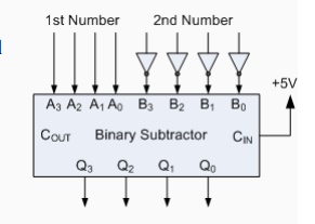
The 4-bit Binary Subtractor
Now that we know how to "ADD" together two 4-bit
binary numbers how would we subtract two 4-bit binary numbers, for example, A -
B using the circuit above. The answer is to use 2‘s-complement notation on all
the bits in B must be complemented (inverted) and an extra one added using the
carry-input. This can be achieved by inverting each B input bit using an
inverter or NOT-gate.
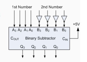
Also, in the above circuit for the 4-bit binary adder, the first
carry-in input is held LOW at logic "0", for the circuit to perform
subtraction this input needs to be held HIGH at "1". With this in
mind a ripple carry adder can with a small modification be used to perform half
subtraction, full subtraction and/or comparison.
There are a number of 4-bit full-adder ICs available such as the
74LS283 and CD4008. which will add two 4-bit binary number and provide an
additional input carry bit, as well as an output carry bit, so you can cascade
them together to produce 8-bit, 12-bit, 16-bit, etc. adders.
The Binary Adder
Another common and very useful combinational logic circuit which
can be constructed using just a few basic logic gates and adds together binary
numbers is the Binary Adder circuit. The Binary Adder is made up from standard
AND and Ex-OR gates and allow us to "add" together single bit binary
numbers, a and b to produce two outputs, the SUM of the addition and a CARRY
called the Carry-out, ( Cout ) bit. One of the main uses for the Binary Adder
is in arithmetic and counting circuits.
Consider the addition of two denary (base 10) numbers below.
Each column is added together starting from the right hand side
and each digit has a weighted value depending upon its position in the columns.
As each column is added together a carry is generated if the result is greater
or equal to ten, the base number. This carry is then added to the result of the
addition of the next column to the left and so on, simple school math's
addition. The adding of binary numbers is basically the same as that of adding
decimal numbers but this time a carry is only generated when the result in any
column is greater or equal to "2", the base number of binary.
Binary Addition
Binary Addition follows the same basic rules as for the denary
addition above except in binary there are only two digits and the largest digit
is "1", so any "SUM" greater than 1 will result in a
"CARRY". This carry 1 is passed over to the next column for addition
and so on. Consider the single bit addition below.
The single bits are added together and "0 + 0",
"0 + 1", or "1 + 0" results in a sum of "0" or
"1" until you get to "1 + 1" then the sum is equal to
"2". For a simple 1-bit addition problem like this, the resulting
carry bit could be ignored which would result in an output truth table
resembling that of an Ex-OR Gate as seen in the Logic Gates section and whose
result is the sum of the two bits but without the carry. An Ex-OR gate only
produces an output "1" when either input is at logic "1",
but not both. However, all microprocessors and electronic calculators require
the carry bit to correctly calculate the equations so we need to rewrite them
to include 2 bits of output data as shown below.
From the above equations we know that an Ex-OR gate will only
produce an output "1" when "EITHER" input is at logic
"1", so we need an additional output to produce a carry output,
"1" when "BOTH" inputs "A" and "B" are
at logic "1" and a standard AND Gate fits the bill nicely. By
combining the Ex-OR gate with the AND gate results in a simple digital binary
adder circuit known commonly as the "Half Adder" circuit.
The Half Adder Circuit
1-bit Adder with Carry-Out
From the truth table we can see that the SUM (S) output is the
result of the Ex-OR gate and the Carry-out (Cout) is the result of the AND
gate. One major disadvantage of the Half Adder circuit when used as a binary
adder, is that there is no provision for a "Carry-in" from the
previous circuit when adding together multiple data bits. For example, suppose
we want to add together two 8-bit bytes of data, any resulting carry bit would
need to be able to "ripple" or move across the bit patterns starting
from the least significant bit (LSB). The most complicated operation the half
adder can do is "1 + 1" but as the half adder has no carry input the
resultant added value would be incorrect. One simple way to overcome this
problem is to use a Full Adder type binary adder circuit.
The Full Adder Circuit
The main difference between the Full Adder and the previous seen
Half Adder is that a full adder has three inputs, the same two single bit
binary inputs A and B as before plus an additional Carry-In (C-in) input as
shown below.
Full Adder with Carry-In
The 1-bit Full Adder circuit above is basically two half adders
connected together and consists of three Ex-OR gates, two AND gates and an OR
gate, six logic gates in total. The truth table for the full adder includes an
additional column to take into account the Carry-in input as well as the summed
output and carry-output. 4-bit full adder circuits are available as standard IC
packages in the form of the TTL 74LS83 or the 74LS283 which can add together
two 4-bit binary numbers and generate a SUM and a CARRY output. But what if we
wanted to add together two n-bit numbers, then n 1-bit full adders need to be
connected together to produce what is known as the Ripple Carry Adder.
The 4-bit Binary Adder
The Ripple Carry Binary Adder is simply n, full adders cascaded
together with each full adder represents a single weighted column in the long
addition with the carry signals producing a "ripple" effect through
the binary adder from right to left. For example, suppose we want to
"add" together two 4-bit numbers, the two outputs of the first full adder
will provide the first place digit sum of the addition plus a carry-out bit
that acts as the carry-in digit of the next binary adder. The second binary
adder in the chain also produces a summed output (the 2nd bit) plus another
carry-out bit and we can keep adding more full adders to the combination to add
larger numbers, linking the carry bit output from the first full binary adder
to the next full adder, and so forth. An example of a 4-bit adder is given
below.
A 4-bit Binary Adder
One main disadvantage of "cascading" together 1-bit
binary adders to add large binary numbers is that if inputs A and B change, the
sum at its output will not be valid until any carry-input has
"rippled" through every full adder in the chain.
Consequently, there will be a finite delay before the output of
a adder responds to a change in its inputs resulting in the accumulated delay
especially in large multi-bit binary adders becoming prohibitively large. This
delay is called Propagation delay. Also "overflow" occurs when an
n-bit adder adds two numbers together whose sum is greater than or equal to 2n
One solution is to generate the carry-input signals directly
from the A and B inputs rather than using the ripple arrangement above. This
then produces another type of binary adder circuit called a Carry Look Ahead
Binary Adder were the speed of the parallel adder can be greatly improved using
carry-look ahead logic.
The 4-bit Binary Subtractor
Now that we know how to "ADD" together two 4-bit
binary numbers how would we subtract two 4-bit binary numbers, for
example, A - B using the circuit above. The answer is to use
2‘s-complement notation on all the bits in B must be complemented (inverted)
and an extra one added using the carry-input. This can be achieved by inverting
each B input bit using an inverter or NOT-gate.
Also, in the above circuit for the 4-bit binary adder, the first carry-in input is held LOW at logic "0", for the circuit to perform subtraction this input needs to be held HIGH at "1". With this in mind a ripple carry adder can with a small modification be used to perform half subtraction, full subtraction and/or comparison.
There are a number of 4-bit full-adder ICs available such as the
74LS283 and CD4008. which will add two 4-bit binary number and provide an
additional input carry bit, as well as an output carry bit, so you can cascade
them together to produce 8-bit, 12-bit, 16-bit, etc. adders.
Related Topics