Chapter: Linear Integrated Ciruits : Application of Op-Amp
Application of Op-Amp
APPLICATION OF OP-AMP
The basic inverting amplifier configuration using an op-amp with input impedance Z1 and feedback impedance Zf .
If the
impedance Z1 and Zf are equal in
magnitude and phase, then the closed loop voltage gain is -1,and the input
signal will undergo a 1800 phase shift at the output. Hence, such
circuit is also called phase inverter. If two such amplifiers are connected in
cascade, then the output from the second stage is the same as the input signal
without any change of sign.
Hence,
the outputs from the two stages are equal in magnitude but opposite in phase
and such a system is an excellent paraphase amplifier
Referring
the above diagram, if the ratio Zf / Z1 = k, a real constant,
then the closed loop gain is –k, and the input voltage is multiplied by a
factor –k and the scaled output is available at the output. Usually, in such
applications, Zf and Z1 are selected as precision
resistors for obtaining precise and scaled value of input voltage.
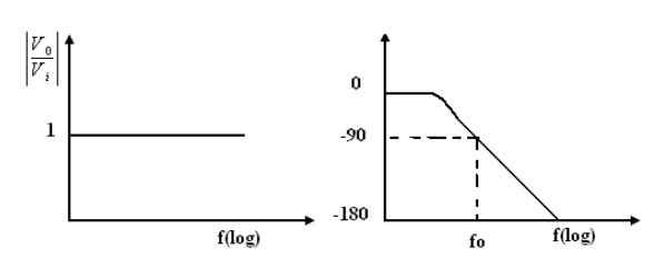
1. PHASE SHIFT CIRCUITS
The phase
shift circuits produce phase shifts that depend on the frequency and maintain a
constant gain. These circuits are also called constant-delay filters or
all-pass filters. That constant delay refers to the fact the time difference
between input and output remains constant when frequency is changed over a
range of operating frequencies.
This is
called all-pass because normally a constant gain is maintained for all the
frequencies within the operating range. The two types of circuits, for lagging
phase angles and leading phase angles.
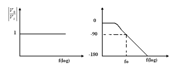
2. Phase-lag circuit:
Phase log
circuit is constructed using an op-amp, connected in both inverting and non
inverting modes. To analyze the circuit operation, it is assumed that the input
voltage v1 drives a simple inverting amplifier with inverting input applied
at(-)terminal of op-amp and a non inverting amplifier with a low-pass filter.
It is
also assumed that inverting gain is -1 and non-inverting gain after the
low-pass circuit
The
relationship is complex as defined above equation and it shows that it has both
magnitude and phase. Since the numerator and denominator are complex
conjugates, their
Related Topics