Chapter: Digital Principles and System Design : Asynchronous Sequential Circuits
Analysis of Asynchronous Sequential circuits
ASYNCHRONOUS SEQUENTIAL CIRCUITS
PRE-REQUISITE
DISCUSSION
The communication of two units, with each unit having its own
independent clock, must be done with asynchronous circuits.
·
Do not use clock pulses. The change of internal
state occurs when there is a change in the input variable.
·
Their memory elements are either unclocked
flip-flops or time-delay elements.
·
They often resemble combinational circuits with
feedback.
·
Their synthesis is much more difficult than the
synthesis of clocked synchronous sequential circuits.
·
They are used when speed of operation is
important.
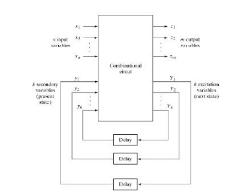
ANALYSIS PROCEDURE
The analysis of asynchronous sequential circuits proceeds in
much the same way as that of clocked Synchronous sequential circuits. From a
logic diagram, Boolean expressions are written and then transferred into
tabular form.
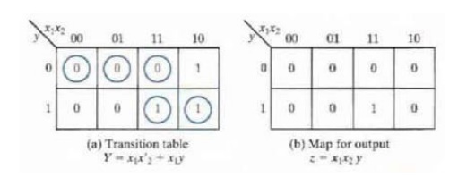
ü Transition Table
The analysis of the circuit starts by considering the excitation
variables (Y1 and Y2) as outputs and the secondary variables (y1 and y2) as
inputs.
The circuit has four stable total
states, =000,011,110, and 101 and four unstable total states-001,010,111 and
100.
The state table of the circuit is shown below:
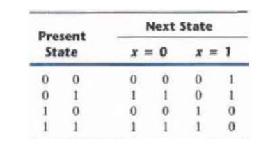
This table provides the same information as the transition
table.
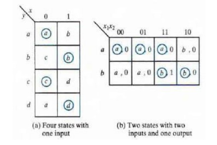
ü Flow table
In a flow table the states are named by letter symbols.
Examples of flow tables are as follows:
In order to obtain the circuit
described by a flow table, it is necessary to assign to each state a distinct
value.
This assignment converts the flow table into a transition
table. This is shown below,
The resulting logic diagram is shown below,
ü Race Conditions
A race condition exists in an
asynchronous circuit when two or more binary state variables change value in
response to a change in an input variable. When unequal delays are encountered,
a race condition may cause the state variable to change in an unpredictable
manner.
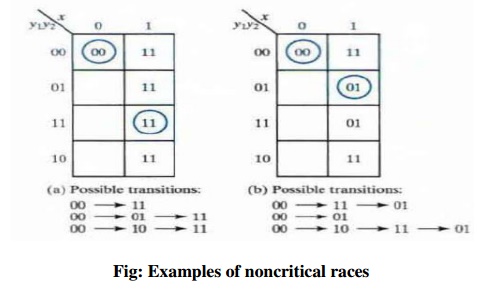
If the final stable state that the circuit reaches does not
depend on the order in which the state variables change, the race is called a
noncritical race. Examples of noncritical races are illustrated in the
transition tables below:
The transition tables below illustrate critical races:
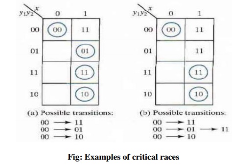
Fig:
Examples of critical races
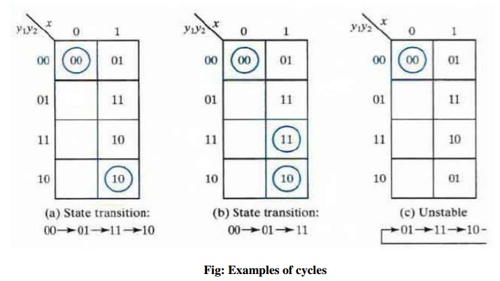
Races can be avoided by directing the circuit through a unique
sequence of intermediate unstable states. When a circuit does that, it is said
to have a cycle. Examples of cycles are:
ü Stability Considerations
An asynchronous sequential circuit may become unstable and
oscillate between unstable states because of the presence of feedback. The
instability condition can be detected from the transition table. Consider the
following circuit:
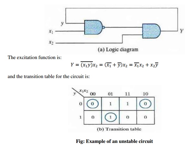
Those values of Y that are equal
to y are circled and represent stable states. When the input x1x2 is 11, the
state variable alternates between 0 and 1 indefinitely.
CIRCUITS WITH SR LATCHES
The SR latch is used as a time-delay element in
asynchronous sequential circuits. The NOR gate SR latch and its truth table
are:
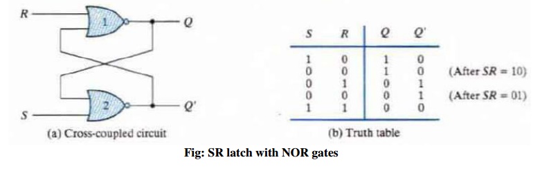
Fig: SR latch with NOR gates
The feedback is more visible when the circuit is
redrawn as:
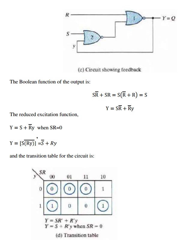
The behavior of the SR latch can
be investigated from the transition table. The condition to be avoided is that
both S and R inputs must not be 1 simultaneously. This condition is avoided
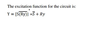
when SR = 0 (i.e., ANDing of S and R must always result in 0). When SR = 0
holds at all times, the excitation function
derived previously:
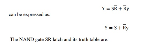
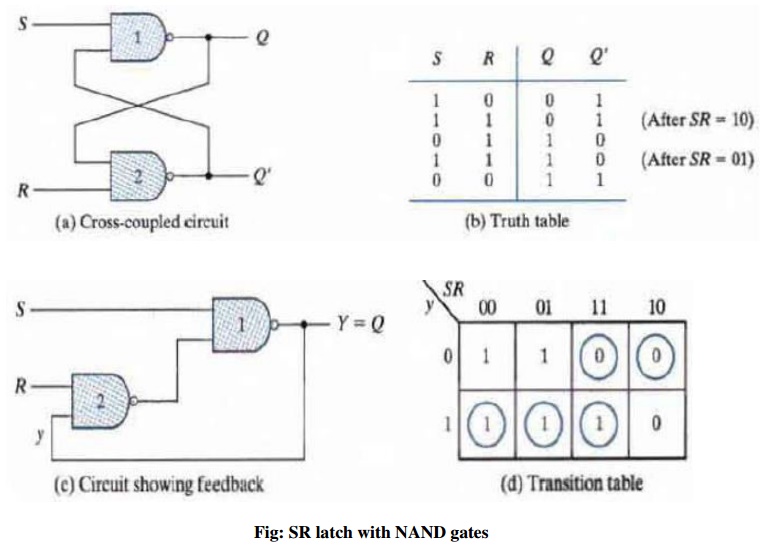
Fig: SR
latch with NAND gates
The condition to be avoided here is that both S and R not be 0
simultaneously which is satisfied when
S′R′ = 0.
ANALYSIS EXAMPLE
Consider the following circuit:

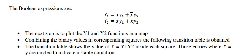
The first step is to obtain the Boolean functions
for the S and R inputs in each latch:
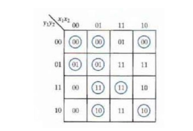
Investigation of the transition
table reveals that the circuit is stable. There is a critical race condition
when the circuit is initially in total state y1y2x1x2 = 1101 and x2 changes
from 1 to 0. If Y1 changes to 0 before Y2, the circuit goes to total state 0100
instead of 0000.
SR Latch Excitation Table
Excitation table lists the
required inputs S and R for each of the possible transitions from the secondary
variable y to the excitation variable Y.
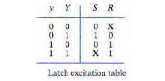
Useful for obtaining the Boolean
functions for S and R and the circuit’s logic diagram
from a give transition table.
Implementation Example
Consider the following transition
table:
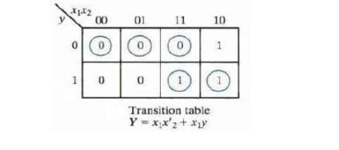
From the information given in the transition table and the SR
latch excitation table, we can obtain maps for the S and R inputs of the latch:
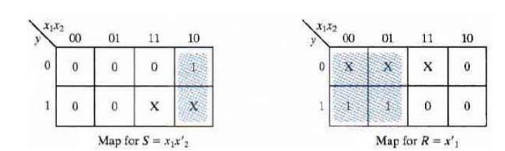
X represents a don’t
care condition.
The maps are then used
to derive the simplified Boolean functions:

The logic diagram
consists of an SR latch and gates required to implement the S and R Boolean
functions. The circuit when a NOR SR latch is used is as shown below:
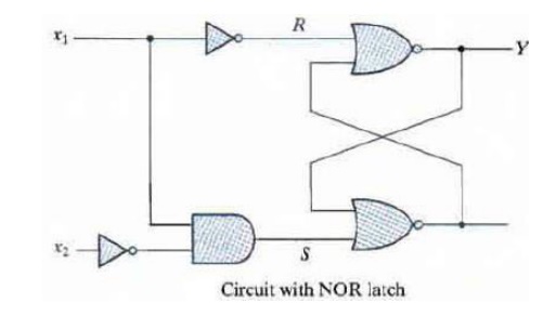
With a
NAND SR latch the complemented values for S and R must be used.
Related Topics