A/D and D/A converters - Analog and Digital Data Conversions | Linear Integrated Circuits : Analog to Digital And Digital to Analog Converters
Chapter: Linear Integrated Circuits : Analog to Digital And Digital to Analog Converters
Analog and Digital Data Conversions
Analog To
Digital Conversion
The
natural state of audio and video signals is analog. When digital technology was
not yet around, they are recorded or played back in analog devices like vinyl
discs and cassette tapes. The storage capacity of these devices is limited and
doing multiple runs of re-recording and editing produced poor signal quality.
Developments in digital technology like the CD, DVD, Blu-ray, flash devices and
other memory devices addressed these problems.
For
these devices to be used, the analog signals are first converted to digital
signals using analog to digital conversion (ADC). For the recorded audio and video signals to be heard and viewed
again, the reverse process of digital to analog conversion (DAC) is used.
ADC
and DAC are also used in interfacing digital circuits to analog systems.
Typical applications are control and monitoring of temperature, water level,
pressure and other real-world data.
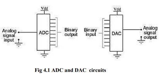
An
ADC inputs an analog signal such as voltage or current and outputs a digital
signal in the form of a binary number. A DAC, on the other hand, inputs the
binary number and outputs the corresponding analog voltage or current signal.
Sampling rate
The
analog signal is continuous in time and it is necessary to convert this to a
flow of digital values. It is therefore required to define the rate at which
new digital values are sampled from the analog signal. The rate of new values
is called the sampling rate or sampling frequency of the converter.
A
continuously varying band limited signal can be sampled (that is, the signal
values at intervals of time T, the sampling time, are measured and stored) and
then the original signal can be exactly
reproduced from the discrete-time values by an interpolation formula. The
accuracy is limited by quantization error. However, this faithful reproduction
is only possible if the sampling rate is higher than twice the highest
frequency of the signal. This is essentially what is embodied in the
Shannon-Nyquist sampling theorem.
Since
a practical ADC cannot make an instantaneous conversion, the input value must
necessarily be held constant during the time that the converter performs a
conversion (called the conversion time).
An input circuit called a sample and
hold performs this task—in most cases by using a capacitor to store the analog voltage at the input, and using an
electronic switch or gate to disconnect the capacitor from the input. Many ADC
integrated circuits include the sample and hold subsystem internally.
Accuracy
An
ADC has several sources of errors. Quantization error and (assuming the ADC is
intended to be linear) non-linearity is intrinsic to any analog-to-digital
conversion. There is also a so-called aperture
error which is due to a clock jitter and is revealed when digitizing a
time-variant signal (not a constant value).
These
errors are measured in a unit called the LSB,
which is an abbreviation for least significant bit. In the above example of an
eight-bit ADC, an error of one LSB is 1/256 of the full signal range, or about
0.4%.
Quantization error
Quantization
error is due to the finite resolution of the ADC, and is an unavoidable
imperfection in all types of ADC. The magnitude of the quantization error at
the sampling instant is between zero and half of one LSB.
In
the general case, the original signal is much larger than one LSB. When this
happens, the quantization error is not correlated with the signal, and has a
uniform distribution.
Its
RMS value is the standard deviation of this distribution, given by 1/√12 LSB ≈ 0.289LSB. In the eight-bit ADC
example, this represents 0.113% of the full signal range.
At
lower levels the quantizing error becomes dependent of the input signal,
resulting in distortion. This distortion is created after the anti-aliasing filter,
and if these distortions are above 1/2 the sample rate they will alias back
into the audio band. In order to make the Quantizing error independent of the
input signal, noise with amplitude of 1 quantization step is added to the
signal. This slightly reduces signal to noise ratio, but completely eliminates
the distortion. It is known as dither.
Non-linearity
All
ADCs suffer from non-linearity errors caused by their physical imperfections,
resulting in their output to deviate from a linear function (or some other
function, in the case of a deliberately non-linear ADC) of their input. These
errors can sometimes be mitigated by calibration, or prevented by testing.
Important
parameters for linearity are integral non-linearity (INL) and differential non-
linearity (DNL). These non-linear ties reduce the dynamic range of the signals
that can be digitized by the ADC, also reducing the effective resolution of the
ADC.
D To A Converter- Specifications
D/A
converters are available with wide range of specifications specified by
manufacturer. Some of the important specifications are Resolution, Accuracy,
linearity, monotonicity, conversion time, settling time and stability.
Resolution:
Resolution
is defined as the number of different analog output voltage levels that can be
provided by a DAC. Or alternatively resolution is defined as the ratio of a
change in output voltage resulting for a change of 1 LSB at the digital input.
Simply, resolution is the value of LSB.
Resolution
(Volts) = VoFS / (2n - 1) = 1 LSB
increment
Where ‘n’ is the number of input bits
‘VoFS’
is the full scale output voltage.
Example:
Resolution
for an 8 – bit DAC for example is said to have
: 8 – bit resolution
: A resolution of 0.392 of full-Scale (1/255)
: A resolution of 1 part in 255.
Thus resolution can be defined in many different ways.
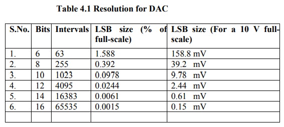
The following table shows the resolution for 6 to 16 bit DACs
Accuracy:
Absolute
accuracy is the maximum deviation between the actual converter output and the
ideal converter output. The ideal converter is the one which does not suffer
from any problem. Whereas, the actual converter output deviates due to the
drift in component values, mismatches, aging, noise and other sources of
errors.
The
relative accuracy is the maximum deviation after the gain and offset errors
have been removed. Accuracy is also given in terms of LSB increments or
percentage of full-scale voltage. Normally, the data sheet of a D/A converter
specifies the relative accuracy rather than absolute accuracy.
Linearity:
Linearity
error is the maximum deviation in step size from the ideal step size. Some D/A
converters are having a linearity error as low as 0.001% of full scale. The
linearity of a D/A converter is defined as the precision or exactness with
which the digital input is converted into analog output. An ideal D/A converter
produces equal increments or step sizes at output for every change in equal
increments of binary input.
Monotonicity:
A
Digital to Analog converter is said to be monotonic if the analog output
increases for an increase in the digital input. A monotonic characteristic is
essential in control applications. Otherwise it would lead to oscillations. If
a DAC has to be monotonic, the error should be less than ± (1/2) LSB at each
output level. Hence all the D/A converters are designed such that the linearity
error satisfies the above condition.
When
a D/A Converter doesn’t satisfy the condition described above, then, the output
voltage may decrease for an increase in the binary input.
Conversion Time:
It
is the time taken for the D/A converter to produce the analog output for the
given binary input signal. It depends on the response time of switches and the
output of the Amplifier. D/A converters speed can be defined by this parameter.
It is also called as setting time.
Settling time:
It
is one of the important dynamic parameter. It represents the time it takes for
the output to settle within a specified band ± (1/2) LSB of its final value
following a code change at the input (Usually a full-scale change). It depends
on the switching time of the logic circuitry due to internal parasitic
capacitances and inductances. A typical settling time ranges from 100 ns to 10
µs depending on the word length and type of circuit used.
Stability:
The
ability of a DAC to produce a stable output all the time is called as
Stability. The performance of a converter changes with drift in temperature,
aging and power supply variations. So all the parameters such as offset, gain,
linearity error & monotonicity may change from the values specified in the
datasheet. Temperature sensitivity defines the stability of a D/A converter.
Related Topics