Chapter: Satellite Communication : Satellite Access
Analog - digital transmission system
Analog - digital
transmission system :
1. Analog vs.
Digital Transmission:
Compare
at two levels:
1.
Data—continuous (audio) vs. discrete (text)
2.
Signaling—continuously varying electromagnetic wave vs. sequence of voltage
pulses.
Also
Transmission—transmit without regard to signal content vs. being concerned with
signal content. Difference in how attenuation is handled, but not focus on
this.Seeing a shift towards digital transmission despite large analog base.
Why?
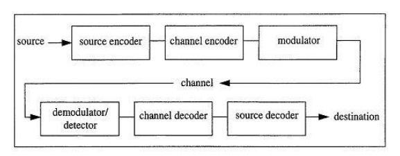
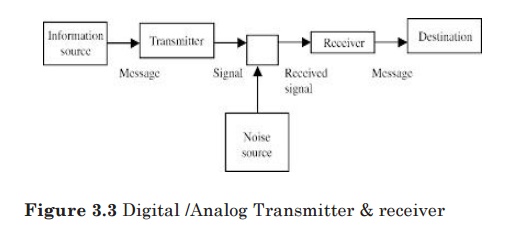
Figure
3.2 basic communication systems
•
Improving digital technology
•
Data integrity. Repeaters take out cumulative problems in transmission.
•
Can thus transmit longer distances.
•
Easier to multiplex large channel capacities with digital
•
Easy to apply encryption to digital data
•
Better integration if all signals are in one form. Can integrate voice, video
and digital data.
2. Digital
Data/Analog Signals:
Must
convert digital data to analog signal such device is a modem to translate
between bit-serial and modulated carrier signals?
To
send digital data using analog technology, the sender generates a carrier
signal at some continuous tone (e.g. 1-2 kHz in phone circuits) that looks like
a sine wave. The following techniques are used to encode digital data into
analog signals.
Resulting
bandwidth is centered on the carrier frequency.
•
Amplitude-shift modulation (keying): vary the amplitude (e.g. voltage) of the
signal. Used to transmit digital data over optical fiber.
• Frequency-shift modulation:
two (or more tones) are used, which are near
the carrier frequency. Used in a full-duplex modem (signals in both
directions).
• Phase-shift modulation: systematically
shift the carrier wave at uniformly spaced intervals.
For
instance, the wave could be shifted by 45, 135, 225, 315 degree at each timing
mark. In this case, each timing interval carries 2 bits of information.
Why
not shift by 0, 90, 180, 270? Shifting zero degrees means no shift, and an
extended set of no shifts leads to clock synchronization difficulties.
Frequency division multiplexing
(FDM): Divide the frequency spectrum into smaller
subchannels, giving each user exclusive use of a subchannel (e.g., radio and
TV). One problem with FDM is that a user is given all of the frequency to use,
and if the user has no data to send, bandwidth is wasted — it cannot be used by
another user.
Time division multiplexing (TDM): Use
time slicing to give each user the full bandwidth, but for only a fraction of a
second at a time (analogous to time sharing in operating systems). Again, if
the user doesn’t have data to sent during his timeslice, the bandwidth is not
used (e.g., wasted).
Statistical multiplexing: Allocate
bandwidth to arriving packets on demand. This leads to the most efficient use
of channel bandwidth because it only carries useful data.That is, channel
bandwidth is allocated to packets that are waiting for transmission, and a user
generating no packets doesn’t use any of the channel resources.
Related Topics