Chapter: Electrical machines : Three Phase Induction Motor
Alternate Analysis for Rotating Magnetic Field
Alternate Analysis for Rotating Magnetic Field
When a 3-phase winding is energized from a 3-phase supply, a rotating magnetic field is produced. This field is such that its poles do no remain in a fixed position on the stator but go on shifting their positions around the stator. For this reason, it is called a rotating Held. It can be shown that magnitude of this rotating field is constant and is equal to 1.5 m where m is the maximum flux due to any phase.
To see how rotating field is produced, consider a 2-pole, 3-phase winding as shown in Fig. 3.6 (i). The three phases X, Y and Z are energized from a 3-phase source and currents in these phases are indicated as Ix, Iy and Iz [See Fig. 3.6 (ii)]. Referring to Fig. 3.6 (ii), the fluxes produced by these currents are given by:
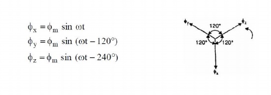
Here ϕm is the maximum flux due to any phase. Above figure shows the phasor diagram of the three fluxes. We shall now prove that this 3-phase supply produces a rotating field of constant magnitude equal to 1.5 ϕm.
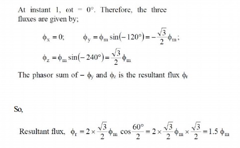
At instant 1 [See Fig. 3.6 (ii) and Fig. 3.6 (iii)], the current in phase X is zero and currents in phases Y and Z are equal and opposite. The currents are flowing outward in the top conductors and inward in the bottom conductors. This establishes a resultant flux towards right. The magnitude of the resultant flux is constant and is equal to 1.5 ϕm as proved under:
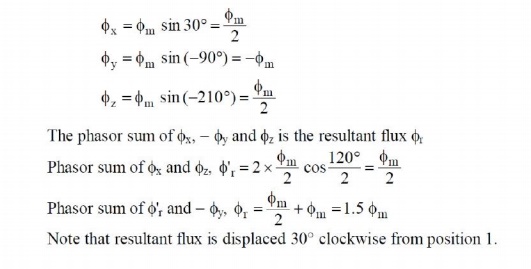
At instant 2 [Fig: 3.7 (ii)], the current is maximum (negative) in ϕy phase Y and 0.5 maximum (positive) in phases X and Y. The magnitude of resultant flux is 1.5ϕm as proved under:
At instant 2, ωt = 30°. Therefore, the three fluxes are given by;
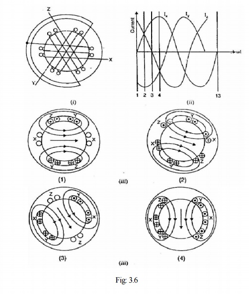
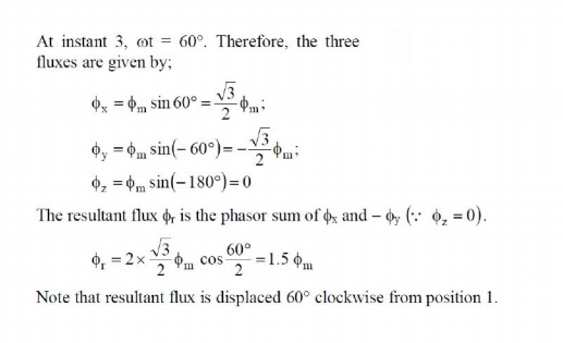
At instant 3[Fig: 3.7 (iii)], current in phase Z is zero and the currents in phases X and Y are equal and opposite (currents in phases X and Y arc 0.866 max. value). The magnitude of resultant flux is 1.5 ϕm as proved under:
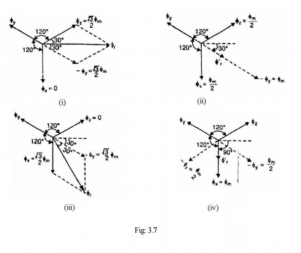
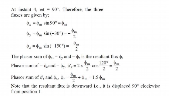
At instant 4 [Fig: 3.7 (iv)], the current in phase X is maximum (positive) and the currents in phases V and Z are equal and negative (currents in phases V and Z are 0.5 ϕ max. value). This establishes a resultant flux downward as shown under:
It follows from the above discussion that a 3-phase supply produces a rotating field of constant value (= 1.5 ϕm, where ϕm is the maximum flux due to any phase).
1. Speed of rotating magnetic field
The speed at which the rotating magnetic field revolves is called the synchronous speed (Ns).
Referring to Fig. 3.6 (ii), the time instant 4 represents the completion of one-quarter cycle of alternating current Ix from the time instant 1. During this one quarter cycle, the field has rotated through 90°. At a time instant represented by 13 [Fig. 3.6 (ii)] or one complete cycle of current Ix from the origin, the field has completed one revolution. Therefore, for a 2-pole stator winding, the field makes one revolution in one cycle of current. In a 4-pole stator winding, it can be shown that the rotating field makes one revolution in two cycles of current. In general, fur P poles, the rotating field makes one revolution in P/2 cycles of current.

The speed of the rotating magnetic field is the same as the speed of the alternator that is supplying power to the motor if the two have the same number of poles. Hence the magnetic flux is said to rotate at synchronous speed.
2. Direction of rotating magnetic field
The phase sequence of the three-phase voltage applied to the stator winding in Fig. 3.6 (ii) is X-Y-Z. If this sequence is changed to X-Z-Y, it is observed that direction of rotation of the field is reversed i.e., the field rotates counter clockwise rather than clockwise. However, the number of poles and the speed at which the magnetic field rotates remain unchanged. Thus it is necessary only to change the phase sequence in order to change the direction of rotation of
the magnetic field. For a three-phase supply, this can be done by interchanging any two of the three lines. As we shall see, the rotor in a 3-phase induction motor runs in the same direction as the rotating magnetic field. Therefore, the direction of rotation of a 3-phase induction motor can be reversed by interchanging any two of the three motor supply lines.
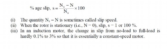
3. Slip
We have seen above that rotor rapidly accelerates in the direction of rotating field. In practice, the rotor can never reach the speed of stator flux. If it did, there would be no relative speed between the stator field and rotor conductors, no induced rotor currents and, therefore, no torque to drive the rotor. The friction and windage would immediately cause the rotor to slow down. Hence, the rotor speed (N) is always less than the suitor field speed (Ns). This difference in speed depends upon load on the motor. The difference between the synchronous speed Ns of the rotating stator field and the actual rotor speed N is called slip. It is usually expressed as a percentage of synchronous speed i.e.
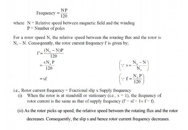
4. Rotor Current Frequency
The frequency of a voltage or current induced due to the relative speed between a vending and a magnetic field is given by the general formula;
Related Topics