Phasor diagram, Circuit Diagram, Formula, Solved Example Problems | Alternating Current (AC) - AC circuit containing a resistor, an inductor and a capacitor in series - Series RLC circuit | 12th Physics : Electromagnetic Induction and Alternating Current
Chapter: 12th Physics : Electromagnetic Induction and Alternating Current
AC circuit containing a resistor, an inductor and a capacitor in series - Series RLC circuit
AC circuit containing a resistor, an inductor
and a capacitor in series - Series RLC circuit
Consider a circuit
containing a resistor of resistance R, a inductor of inductance L
and a capacitor of capacitance C connected across an alternating voltage
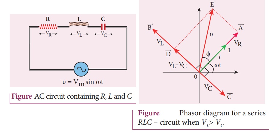
source (Figure 4.51). The applied alternating voltage is given by the equation.
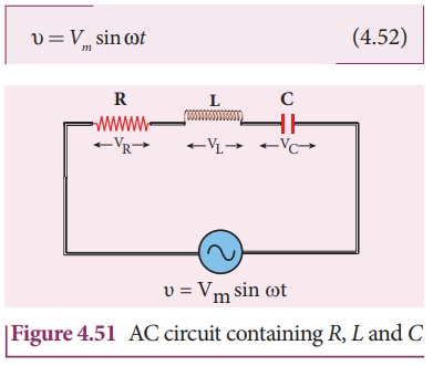
Let i be the resulting
circuit current in the circuit at that instant. As a result, the voltage is
developed across R, L and C. We know that voltage across R (VR) is
in phase with i, voltage across L (VL) leads i by ŽĆ/2 and voltage
across C (VC) lags i by ŽĆ/2.
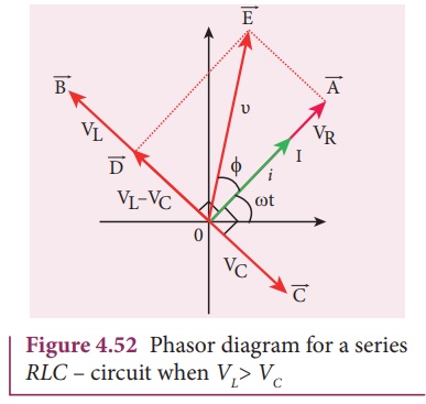
The phasor diagram is drawn with current as the reference phasor. The current is represented by the phasor
 as shown in Figure 4.52.
The length of these
phasors are
OI = Im, OA = ImR, OB = ImXL; OC = ImXC
The circuit is either
effectively inductive or capacitive or resistive that depends on the value of VL
or VC. Let us assume that VL > VC
so that net voltage drop across L-C combination is VL
ŌĆō VC which is represented by a phasor ![]() .
.
By parallelogram law,
the diagonal ![]() gives the resultant voltage Žģ of VR
and (VL ŌĆō VC) and its length OE
is equal to Vm. Therefore,
gives the resultant voltage Žģ of VR
and (VL ŌĆō VC) and its length OE
is equal to Vm. Therefore,
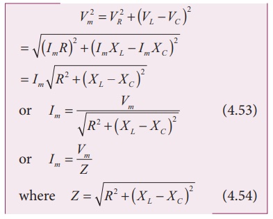
Z is called impedance of
the circuit which refers to the effective opposition to the circuit
current by the series RLC circuit. The voltage triangle and impedance
triangle are given in the Figure 4.53.
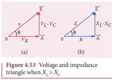
From phasor diagram, the
phase angle between Žģ and i is found out from the following
relation
Special cases
(i) If XL
> XC, (XLŌłÆXC) is
positive and phase angle ŽĢ is also positive. It means that the applied voltage
leads the current by ŽĢ (or current lags behind voltage by ŽĢ). The circuit is
inductive.
Ōł┤
Žģ = Vm sin Žēt; i = I m
sin( Žē t ŌłÆŽå)
(ii) If XL
< XC, (XL ŌłÆ XC) is
negative and ŽĢ is also negative. Therefore current leads voltage by ŽĢ and the circuit
is capacitive.
Ōł┤ Žģ
= Vm sin Žēt; i = I m sin( Žē t + Žå)
(iii) If XL
= XC, ŽĢ is zero. Therefore current and voltage are in the
same phase and the circuit is resistive.![]()
![]()
Ōł┤
Žģ =Vm sin Žēt; i = Im
sin Žēt
Related Topics