Chapter: Fundamentals of Database Systems : Conceptual Modeling and Database Design : Data Modeling Using the Entity-Relationship (ER) Model
A Sample Database Application
A Sample Database Application
In this section we describe a sample database application, called COMPANY, which serves to illustrate the basic ER model concepts and their use
in schema design. We list the data requirements for the database here, and then
create its conceptual schema step-by-step as we introduce the modeling concepts
of the ER model. The COMPANY database keeps track of a
company’s employees, departments, and projects. Suppose that after the
requirements collection and analysis phase, the database designers provide the
following description of the miniworld—the
part of the company that will be represented in the database.
The company is organized into
departments. Each department has a unique name, a unique number, and a
particular employee who manages the department. We keep track of the start date
when that employee began man-aging the department. A department may have
several locations.
A department controls a number of
projects, each of which has a unique name, a unique number, and a single
location.
We store each employee’s name,
Social Security number, address, salary, sex (gender), and birth date. An employee is assigned
to one department, but may work on several projects, which are not necessarily
controlled by the same department. We keep track of the current number of hours
per week that an employee works on each project. We also keep track of the
direct supervisor of each employee (who is another employee).
We want to keep track of the
dependents of each employee for insurance purposes. We keep each dependent’s
first name, sex, birth date, and relation-ship to the employee.
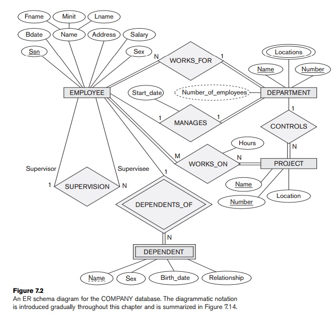
Figure 7.2 shows how the schema for this database application can be
displayed by means of the graphical notation known as ER diagrams. This figure will be explained gradually as the ER model
concepts are presented. We describe the step-by-step process of deriving this
schema from the stated requirements—and explain the ER diagrammatic notation—as
we introduce the ER model concepts.
Related Topics