Chapter: Linear Integrated Circuits : Analog to Digital And Digital to Analog Converters
A/D Using Voltage To Time Conversion
A/D Using
Voltage To Time Conversion:
The
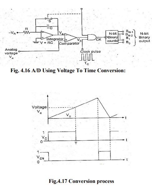
Block diagram shows the basic voltage to time conversion type of A to D
converter. Here the cycles of variable frequency source are counted for a fixed
period. It is possible to make an A/D converter by counting the cycles of a
fixed-frequency source for a variable period. For this, the analog voltage
required to be converted to a proportional time period.
As
shown in the diagram a negative reference voltage -VR is applied to an
integrator, whose output is connected to the inverting input of the comparator.
The output of the comparator is at 1 as long as the output of the integrator Vo
is less than Va.
At
t = T, Vc goes low and switch S remains open. When VEN goes high, the switch S
is closed, thereby discharging the capacitor. Also the NAND gate is disabled.
The waveforms are shown here.
Related Topics